


10
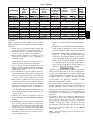
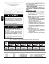
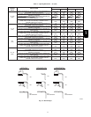
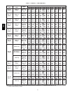
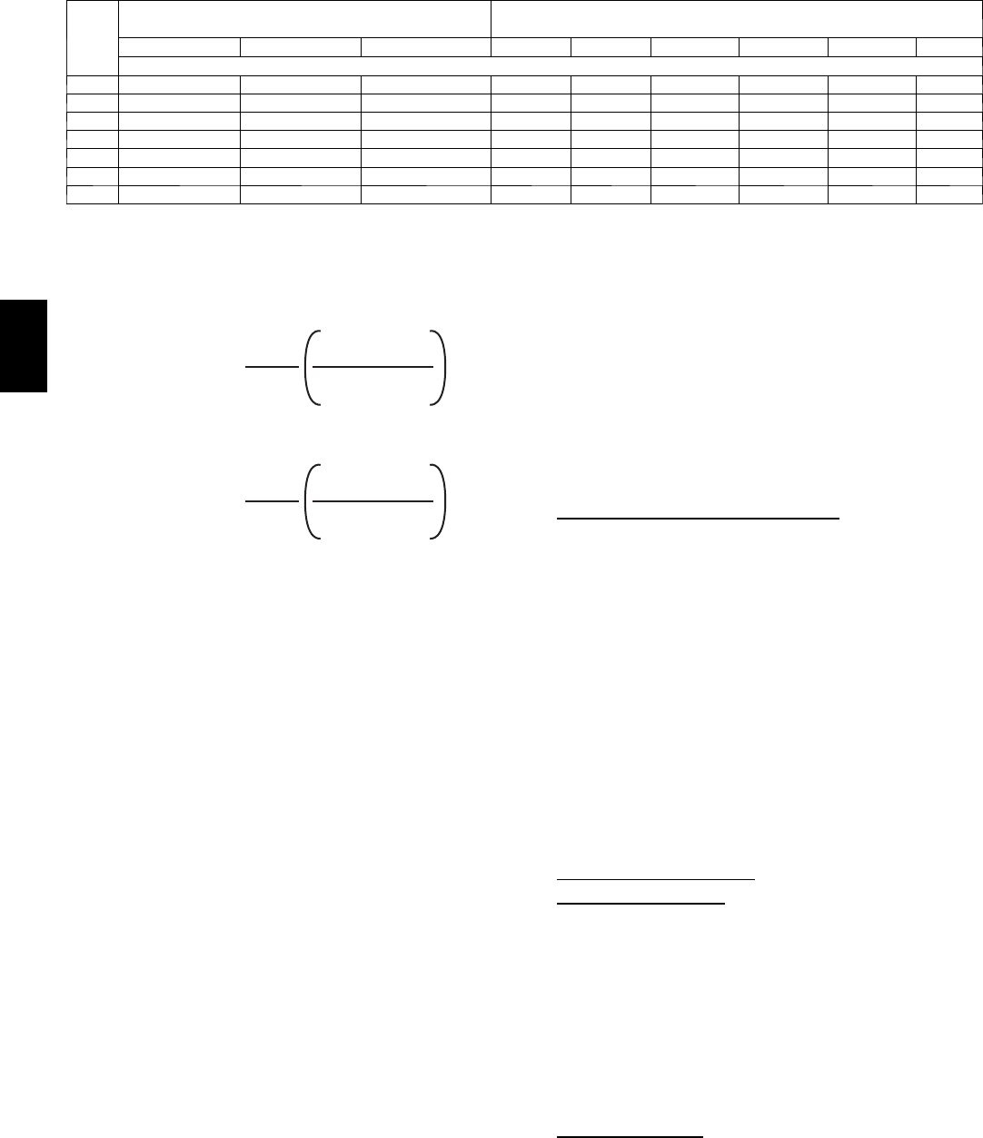
Table 3 – Minimum Space Volumes for 100% Combustion, Ventilation, and Dilution from Indoors
ACH
OTHER THAN FAN---AS SISTED TOTAL
(1,000s BTUH GAS INPUT RATE)
FAN---ASSISTED TOTAL
(1,000s BTUH GAS INPUT RATE)
30 40 50 44 66 88 110 132 154
SpaceVolume(ft.3)
0.60 1,050 1,400 1,750 1,100 1,650 2,200 2,750 3,300 3,850
0.50 1,260 1,680 2,100 1,320 1,980 2,640 3,300 3,960 4,620
0.40 1,575 2,100 2,625 1,650 2,475 3,300 4,125 4,950 5,775
0.30 2,100 2,800 3,500 2,200 3,300 4,400 5,500 6,600 7,700
0.20 3,150 4,200 5,250 3,300 4,950 6,600 8,250 9,900 11,550
0.10 6,300 8,400 10,500 6,600 9,900 13,200 16,500 19,800 23,100
0.00 NP NP NP NP NP NP NP NP NP
NP = Not Permitted
Table 3--Minimum Space Volumes were determined by using
the following equations from the National Fuel Gas Code ANSI
Z223.1--2006/NFPA 54--2006, 9.3.2.2:
1. For other than fan-- assisted appliances, such as a draft
hood--equipped water heater:
Volume
Other
=
21ft
3
ACH
I
other
1000 Btu/hr
A04002
2. For fan--assisted appliances such as this furnace:
Volume
Fan
=
15ft
3
ACH
I
fan
1000 Btu/hr
A04003
If:
I
other
= combined input of all other than fan--assisted
appliances in Btuh/hr
I
fan
= combined input of all fan--assisted appliances in
Btuh/hr
ACH = air changes per hour (ACH shall not exceed 0.60.)
The following requirements apply to the Standard Method and
to the Known Air Infiltration Rate Method.
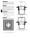
1. Adjoining rooms can be considered part of a space if:
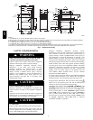
a. There are no closeable doors between rooms.
b. Combining spaces on same floor level. Each opening
shall have free area of at least 1 in.
2
/1,000 Btuh (2,000
mm
2
/kW) of the total input rating of all gas appliances
in the space, but not less than 100 in.
2
(0.06 m
2
). One
opening shall commence within 12 in. (300 mm) of the
ceiling and the second opening shall commence within
12 in. (300 mm) of the floor. The minimum dimension
of air openings shall be at least 3 in. (80 mm). (See Fig.
8.)
c. Combining space on different floor levels. The volumes
of spaces on different floor levels shall be considered as
communicating spaces if connected by one or more per-
manent openings in doors or floors having free area of
at least 2 in.
2
/1,000 Btuh (4,400 mm
2
/kW) of total input
rating of all gas appliances.
2. An attic or crawlspace may be considered a space that
freely communicates with the outdoors provided there are
adequate permanent ventilation openings directly to out-
doors having free area of at least 1--in.2/4,000 Btuh of
total input rating for all gas appliances in the space.
3. In spaces that use the Indoor Combustion Air Method, in-
filtration should be adequate to provide air for combus-
tion, permanent ventilation and dilution of flue gases.
However, in buildings with unusually tight construction,
additional air MUST be provided using the methods de-
scribed in the Outdoor Combustion Air Method section.
Unusually tight construction is defined as Construction
with:
a. Walls and ceilings exposed to the outdoors have a con-
tinuous, sealed vapor barrier. Openings are gasketed or
sealed and
b. Doors and openable windows are weatherstripped and
c. Other openings are caulked or sealed. These include
joints around window and door frames, between sole
plates and floors, between wall--ceiling joints, between
wall panels, at penetrations for plumbing, electrical and
gas lines, etc.
Combination of Indoor and Outdoor
Air
1. Indoor openings shall comply with the Indoor Combus-
tion Air Method below and,
2. Outdoor openings shall be located as required in the Out-
door Combustion Air Method mentioned previously and,
3. Outdoor openings shall be sized as follows:
a. Calculate the Ratio of all Indoor Space volume divided
by required volume for Indoor Combustion Air Meth-
od below.
b. Outdoor opening size reduction Factor is 1 minus the
Ratio in a. above.
c. Minimum size of Outdoor openings shall be the size re-
quired in OutdoorCombustionAirMethod abovemul-
tiplied by reduction Factor in b. above. The minimum
dimension of air openings shall be not less than 3 in. (80
mm).
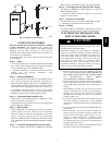
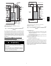
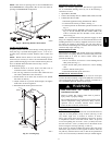
INSTALLATION
UPFLOW INSTALLATION
Bottom Return Air
Inlet
These furnaces are shipped with bottom closure panel installed in
bottom return--air opening. Remove and discard this panel when
bottom return air is used. To remove bottom closure panel,
perform the following:
1. Tilt or raise furnace and remove 2 screws holding bottom
filler panel. (See Fig. 9.)
2. Rotate bottom filler panel downward to release holding
tabs.
3. Remove bottom closure panel.
4. Reinstall bottom filler panel and screws.
Side Return Air
Inlet
These furnaces are shipped with bottom closure panel installed in
bottom return--air opening. This panel MUST be in place when
only side return air is used.
58CT