


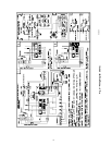
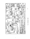

24-V Wiring
Instructions for wiring thermostat (field supplied) are packed in
thermostat box. Make thermostat connections as shown in Fig. 3 or
4 at 24-v terminal board on fan timer board.
Accessories
When installing optional accessories to this appliance, follow
manufacturer’s Installation Instructions included with accessory.
Other than wiring for thermostat, wire with a minimum of type ″T″
insulation (63°F rise) must be used for accessories.
HORIZONTAL OR DOWNFLOW INSTALLATION
For horizontal installation, determine which ″side″ will become the
″top″, when the unit is laid down. Remove the flue pipe clearance
knock-out from the top of that side panel. Install the flue elbow so
that it exits the cabinet of the furnace through that opening.
For counterflow installation, the flue pipe must exit the cabinet
through 1 of the side panel openings (as above), then extended up
the side of the furnace. Insure that adequate clearances to com-
bustibles are observed. Downflow Conversion/Vent Guard Kit
MUST be used.
Remove burner by loosening mounting nuts and turn oil burner
slightly counterclockwise to unlock the key hole burner flange.
Prevent putting undue strain on burner wiring. (It may be neces-
sary to disconnect burner wiring in some cases.)
To reinstall burner, insert on the four burner studs on key hole
burner flange and turn it clockwise to lock it and tighten nuts.
IMPORTANT: Burner must always be installed in the upright
position with ignition control on top.
FILTERS
Never operate unit without a filter or with filter access door
removed. Failure to adhere to this warning could lead to a
hazardous condition which could lead to equipment damage
and bodily harm.
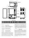
An external filter rack is provided as standard equipment with
furnace. A sufficient clearance should be provided for air filter
access. See Table 8 for filter rack flange dimensions for return air
duct.
START-UP, ADJUSTMENT, AND SAFETY CHECKOUT
Step 1—Operational Checkout
DO NOT TAMPER WITH UNIT OR CONTROLS—CALL
YOUR SERVICE TECHNICIAN. Failure to follow this
warning could result in personal and/or property damage.
Installation of furnace is now complete. Run through the following
checkout and ensure each item has been performed.
1. Correct nozzle size has been selected for desired input rate.
2. Blower wheel support is removed.
3. Electrical wiring is completed according to Fig. 3 or 4.
4. Blower access door is secured in place.
5. Valve on oil supply line is open.
6. RESET BUTTON on primary control is pushed down.
7. Flame observation door and 2 cleanout access doors located at
front of unit are closed.
8. Thermostat is set for heating mode and set above room
temperature.
If all of the above items have been performed, set main electrical
switch to ON position and burner should start. When burner starts,
proceed to Combustion Check section.
Step 2—Combustion Check
In order to obtain optimum performance from oil burner, the
following setup procedures must be followed:
1. A test kit to measure smoke, stack draft, over-fire draft, oil
pump pressure, CO
2
, and stack temperatures MUST be used in
order to obtain proper air band setting. Although all of the
above measurements are required for optimum setup and
efficiency data, the most important readings that must be taken
are smoke number, over-fire draft, stack draft, and pump
pressure.
2. The proper smoke number has been established by engineer-
ing tests to be between 0 and 1. This degree of smoke emission
is commonly referred to as a ″trace″ of smoke. It is recom-
mended to use a Bacharach true spot smoke test set or
equivalent.
3. In order to ensure proper draft through furnace, a barometric
draft regulator (supplied with furnace) must be installed.
In order for this device to function properly, barometric damper
must be mounted with hinge pins horizontal and face of damper
vertical. (See instructions included with damper.) The draft regu-
lator should be adjusted after furnace has been firing for at least 5
minutes, and set between -0.025 and -0.035 in. wc. (See Table 9.)
4. The over-fire draft, which is taken through observation door
(located in center line above burner in front panel of furnace),
is a measurement necessary to determine if there is a blockage
between oil burner and flue outlet.
There should be a total pressure drop of between 0.020 and 0.05 in.
wc through furnace as shown in Table 9. The over-fire draft must
be set within the range shown in Table 9.
A reading outside the range shown in Table 9 (for example +0.1 in.
wc) would indicate that furnace is in an extremely high-pressure
condition in primary section. This condition may be caused by any
of the following problems:
a. Excessive combustion air due to air shutter being too wide
open.
b. A lack of flue draft (chimney effect) or some other
blockage, such as soot, in secondary section of heat
exchanger.
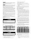
Table 8—Filter and Flange (In.)
UNIT
SIZE
AIR FILTER
SIZE
FLANGE OPENING
SIZE
105-12
16x24x1
or
16X25X1
15X23
120-20 20X30X1 19X29
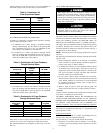
Table 9—Furnace Draft Conditions (In. WC)
FURNACE
INPUT
(BTUH)
FLUE
DRAFT
MINIMUM
OVER-FIRE
DRAFT
MAXIMUM
TOTAL RESTRICTION
THROUGH
HEAT EXCHANGER
70,000 -0.025 0.010 0.020 to 0.035
91,000 -0.025 0.020 0.030 to 0.045
105,000 -0.025 0.025 0.035 to 0.050
119,000 -0.025 0.025 0.035 to 0.050
140,000 -0.025 0.025 0.035 to 0.050
154,000 -0.025 0.025 0.035 to 0.050
7