


c. Use of an oversized nozzle input.
d. Pump pressure over values listed in Table 10.
5. The CO
2
and stack temperature instruments enable you to
obtain data required to determine thermal efficiency of fur-
nace.
6. An oil filter should be installed as close to burner as possible
with ALL oil burners and is essential on lower firing rate
burners. We recommend the use of a low pressure drop oil
filter such as the General Filter, Inc. model #1A-25A or
equivalent.
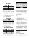
7. The oil pressure regulator is factory set to give oil pressure of
100 psi for the model having 105,000 BTUH input and 100 psi
for the model having 119,000 BTUH input. The firing rate
noted on nameplate may be obtained using the nozzles and
pump pressures indicated in Table 10.
Table 10—Burner Input and Nozzle Size at 100 psi
Pump Pressure
FURNACE
INPUT
(BTUH)
INPUT
USGPH
NOZZLE
REAL PUMP
PRESSURE
SPECIFICATION
PUMP PRESSURE
70,000 0.50 0.50-70W 100 100
91,000 0.65 0.55-70B 140 140
105,000 0.75 0.65-70B 133 130
120,000 0.85 0.75-70B 128 130
140,000 1.00 0.85-70B 138 140
155,000 1.10 0.85-70B 167 170
8. On a new installation, air entrapped in oil line leading from
tank to nozzle must be thoroughly purged in order to prevent
excessive after drip. The oil pump is provided with a special
fitting which allows purging of any air between tank and oil
pump. The proper procedure for performing this operation is
as follows:
a. Place a piece of clear plastic 1/4 in. diameter tubing over
purge fitting on oil pump.
b. Start oil burner, then open purge fitting and allow burner to
run until purge tube is completely free of air bubbles.
c. Tighten purge fitting. Allow oil to run to nozzle and fire
burner.
d. If purging takes longer than 15 sec and no flame has been
established, burner stops. Push reset button on front of
primary control to restart burner.
e. For detailed information on operation of primary control,
refer to instructions included with furnace.
After all the setup procedures mentioned above have been com-
pleted, the burner should be allowed to operate and an inspection
mirror should be used to observe the flame pattern at tip of nozzle.
Any irregularities such as burning to 1 side or pulsating flame
patterns should be corrected by changing nozzle.
Step 3—Fan Adjustment Check
This furnace is equipped with a 4-speed direct-drive motor to
deliver a temperature rise within range specified on rating plate,
between return and supply plenums, at external duct static pressure
noted on rating plate.
When operating furnace in heating mode, static pressure and
temperature rise (supply-air temperature minus return-air
temperature) must be within those limits specified on rating
label. Failure to follow this warning could lead to severe
furnace damage.
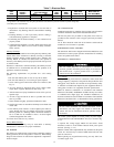
Adjust fan speed ACCORDING TO OIL INPUT SELECTED so
that temperature rise is within rise range specified on rating plate.
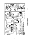
(See Table 11.) Consult wiring diagram for speed changes on
direct-drive motor.
Table 11—Speed Selection
UNIT
SIZE
FURNACE
INPUT
(BTUH)
RECOMMENDED
BLOWER
SPEED
105-12/
120-20
70,000/119,000 Med-Low
91,000/140,000 Med-High
105,000/154,000 High
.
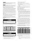
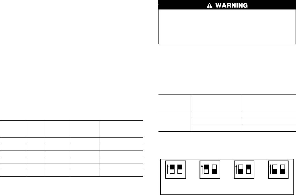
To adjust fan off time, set DIP switches on control board to obtain
desired timing. (See Fig. 5.)
Step 4—Limit Control Check
After furnace has been in operation for at least 15 minutes, restrict
return-air supply by blocking filters or closing return registers and
allow furnace to shut down on high limit. The burner should shut
off, and main blower should continue to run.
Remove restriction, and burner should come back on in a few
minutes.
Step 5—For Year-Round Air Conditioning
This furnace is designed for use in conjunction with cooling
equipment to provide year-round air conditioning. The blower has
been sized for both heating and cooling, however, fan motor speed
may need to be changed to obtain necessary cooling airflow.
Step 6—Heating
The blower speed is factory set to deliver required airflow at
normal duct static pressure.
Step 7—Cooling
The blower speed may be field adjusted to deliver required airflow
for cooling application. (See Table 12.)
Step 8—Constant Blower Switch
This furnace is equipped with a constant low-speed blower option.
Whenever room thermostat is not calling for heating or cooling,
blower runs on low speed in order to provide air circulation. If
constant blower option is not desired, the rocker switch on top of
cabinet may be used to turn off constant speed.
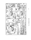
Fig. 5—Fan Off Time DIP Switch Settings
(Black Box Represents Switch Position)
A95115
12
60 Sec
12
90 Sec
DELAY OFF DIP SWITCH SETTINGS
12 1212
120 Sec
12
150 Sec
10
→
→