


ANSI/NFPA 31:
INSTALLATION OF OIL
BURNING EQUIPMENT
ANSI/NFPA 211:
CHIMNEYS, FIREPLACES, VENTS,
AND SOLID FUEL BURNING APPLIANCES
ANSI/NFPA 90B:
WARM AIR HEATING AND AIR
CONDITIONING SYSTEMS
ANSI/NFPA 70: NATIONAL ELECTRICAL CODE
CSA B139:
INSTALLATION CODE FOR
OIL BURNING EQUIPMENT
CAS C22.1: CANADIAN ELECTRICAL CODE
Only the latest issues of these codes should be used, and are
available from either The National Fire Protection Agency, Bat-
terymarch Park, Quincy, MA 02269 or The Canadian Standards
Association, 178 Rexdale Blvd., Rexdale, Ontario M9W 1R3
Recognize safety information. This is the safety-alert symbol
.
When you see this symbol on the furnace and in instructions or
manuals, be alert to the potential for personal injury.
Understand the signal words DANGER, WARNING, CAUTION
and NOTE. These words are used with the safety-alert symbol.
DANGER identifies the most serious hazards which will result in
severe personal injury or death. WARNING signifies a hazard
which could result in personal injury or death. CAUTION is used
to identify unsafe practices which would result in minor personal
injury or product and property damage. NOTE is used to highlight
suggestions which will result in enhanced installation, reliability,
or operation.
INTRODUCTION
The model 58CMA Furnaces are available in 2 sizes. Each size
unit is capable of 3 heat/airflow combinations by a simple nozzle
change. Unit 105-12 covers inputs of 70,000, 91,000, and 105,000
Btuh, and unit 120-20 covers inputs of 119,000, 140,000 and
154,000 Btuh. This eliminates the need to stock 6 separate units.
This furnace is a multipoise unit. It may be installed in the upflow,
downflow or horizontal configuration.
The furnace is shipped as a packaged unit, complete with burner
and controls. It requires a line voltage (115 vac) connection to
control box, a thermostat hook-up as shown on wiring diagram, oil
line connection(s), adequate duct work, and connection to a
properly sized vent.
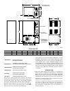
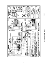
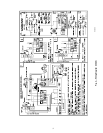
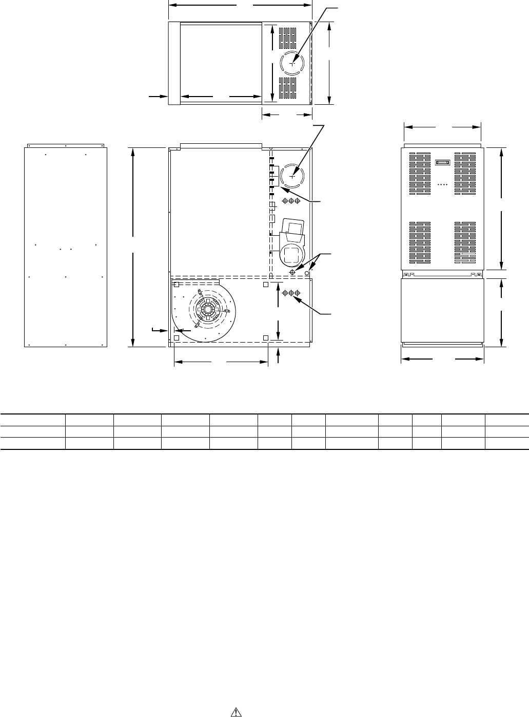
Fig. 2—Dimensional Drawing
Dimensions (IN.)
UNIT SIZE ABCDEFGHJKL
105-12 35 48-3/4 30-1/4 16-5/8 20 22 12 14 5 1-1/2 1-3/4
120-20 39-1/2 53 32-1/4 18-3/4 24 28 12-9/32 16 6 1-5/8 1-1/2
A98037
3″
19″
20″
20″
19″
2″
PULL
OIL INLET
(BOTH SIDES)
VENT CONN
ELECTRICAL
CONNECTIONS
(BOTH SIDES)
.88 DIAM TYP
KNOCK-OUT BOTH SIDES
FOR J DIAM VENT
TOP KNOCK-OUT
FOR J DIAM VENT
A
E
G
B
L
H
C
D
F
K
2
→