


The air handling capacity of this furnace is designed for cooling
airflow. Refer to Table 12 for expected airflows at various external
duct static pressures.
LOCATION
Step 1—General
This furnace is not water tight and is not designed for outdoor
installation. This furnace shall be installed in such a manner
as to protect electrical components from water. Outdoor
installation would lead to a hazardous electrical condition and
to premature furnace failure.
Do not use this furnace as a construction heater. Use of this
furnace as a construction heater exposes furnace to abnormal
conditions, contaminated combustion air, and lack of air
filters. Failure to follow this warning can lead to premature
furnace failure and/or vent failure which could result in a fire
hazard and/or bodily harm.
For attic installation, it is important to keep insulation 12 in.
or more away from any furnace openings. Some types of
insulating materials may be combustibles and may cause a
fire hazard and property damage.
This furnace is approved for reduced clearances to combustible
construction, therefore, it may be installed in a closet or similar
enclosure. Since this unit may be installed in an upflow, counter-
flow, or horizontal position, it may be located in a basement or on
the same level as area to be heated. In any case, unit should always
be installed level.
In a basement, or when installed on floor (as in a crawlspace), it is
recommended that unit be installed on a concrete pad that is 1 in.
to 2 in. thick.
When installed in counterflow position, furnace must not be
installed on combustible flooring, unless approved subbase is used.
Also, since flue pipe is in a counterflow position, Downflow
Conversion/Vent Guard Kit MUST be used. (Also, read page 9.)
When installed in a horizontal position, furnace may be suspended
by using an angle iron frame, as long as total weight of both
furnace and frame are allowed for in support calculations. (Other
methods of suspending are acceptable.) When installed in the
Horizontal Position, this furnace must not be installed on combus-
tible flooring, unless the approved Horizontal Subbase is used.
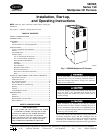
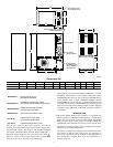
The required minimum clearances for furnace are specified in
Table 1.
The furnace should be located as close as possible to chimney or
vent in order to keep vent connections short and direct. The
furnace should also be located as near as possible to center of air
distribution system.
Step 2—Location Relative to Cooling Equipment
When installing furnace with cooling equipment for year-round
operation, the following recommendations must be followed for
series or parallel airflow:
1. In series airflow applications, coil is mounted after furnace in
an enclosure in supply-air stream. The furnace blower is used
for both heating and cooling airflow.
The coil MUST be installed on air discharge side of furnace.
Under no circumstances should airflow be such that cooled,
conditioned air can pass over furnace heat exchanger. This
will cause condensation in heat exchanger and possible
failure of heat exchanger which could lead to a fire hazard
and/or a hazardous condition which may lead to bodily harm.
Heat exchanger failure due to improper installation may not
be covered by warranty.
2. In parallel airflow applications, dampers must be provided to
direct air over furnace heat exchanger when heat is desired and
over cooling coil when cooling is desired.
IMPORTANT: The dampers should be adequate to prevent cooled
air from entering furnace. If manually operated, dampers must be
equipped with a means to prevent operation of either cooling unit
or furnace unless damper is in full cool or heat position.
INSTALLATION
Step 1—Air for Combustion and Ventilation
Installation of this furnace in an area where it will receive
contaminated combustion air must be avoided. Such contami-
nation would include the following: ammonia, chlorine,
hydrogen sulfide, halogenated hydrocarbons, carbon tetra-
chloride, cleaning solvents, hydrochloric acid, water soften-
ing chemicals, and similar chemicals. Failure to follow this
warning will lead to premature rusting of heat exchanger and
possible premature furnace failure and/or vent failure which
could result in fire hazard and/or bodily harm.
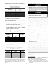
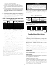
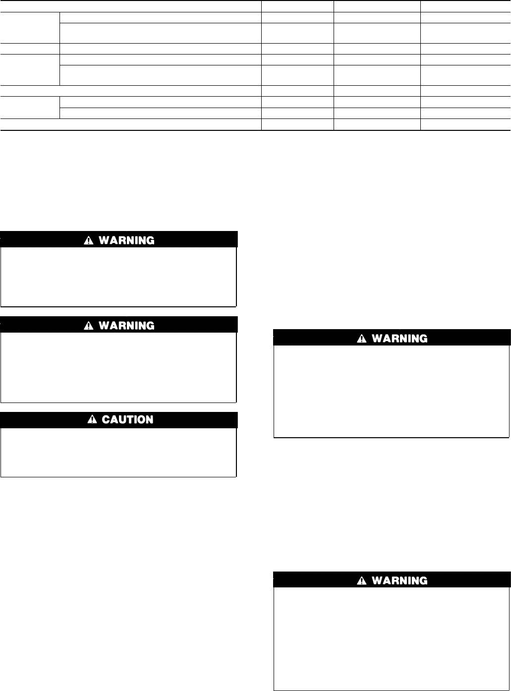
Table 1—Minimum Clearances To Combustible Materials (In.)
UNIT APPLICATION UPFLOW DOWNFLOW HORIZONTAL
Sides
Furnace 0 2 2
Supply Plenum and Warm-Air Duct Within 6 ft
of Furnace
12 1
Back Service Clearance 0 1 0
Top
Furnace Casing or Plenum 2 2 2
Horizontal Warm-Air Duct Within 6 ft of
Furnace
22 3
Bottom 00* 0*
Flue
Pipe
Horizontally or Below Pipe 4 4 4
Vertically Above Pipe 9 9 9
Front 88 24
* Use approved subbase for combustible floor.
NOTE: Adequate service clearances should be provided over and above these dimensions as required.
3