


2. Inspection to ascertain that vent system is clear and free of
obstructions. Any blockage must be cleared before installing
furnace.
3. Cleaning chimney or vent if previously used for venting a
solid fuel burning appliance or fireplace.
4. Confirming that all unused chimney or vent connections are
properly sealed.
5. Verification that chimney is properly lined and sized per the
applicable codes. (Refer to list of codes in Safety Consider-
ations section.)
Masonry Chimneys
This furnace can be vented into an existing masonry chimney. This
furnace must not be vented into a chimney servicing a solid fuel
burning appliance. Before venting furnace into a chimney, the
chimney MUST be checked for deterioration and repaired if
necessary. The chimney must be properly lined and sized per local
or national codes.
If furnace is vented into a common chimney, the chimney must be
of sufficient area to accommodate the total flue products of all
appliances vented into chimney.
The following requirements are provided for a safe venting
system:
1. Be sure that chimney flue is clear of any dirt or debris.
2. Be sure that chimney is not servicing an open fireplace.
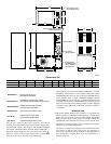
3. Never reduce pipe size below the outlet size of furnace. (See
Fig. 2.)
4. All pipe should be supported using proper clamps and/or
straps. These supports should be at least every 4 ft.
5. All horizontal runs of pipe should have at least 1/4-in. per ft of
upward slope.
6. All runs of pipe should be as short as possible with as few
turns as possible.
7. Seams should be tightly joined and checked for leaks.
8. The flue pipe must not extend into chimney but be flush with
inside wall.
9. The chimney must extend 3 ft above highest point where it
passes through the roof of a building and at least 2 ft higher
than any portion of a building within a horizontal distance of
10 ft. It shall also be extended at least 5 ft above highest
connected equipment flue collar.
10. Check local codes for any variance.
Factory-Built Chimneys
Listed factory-built chimneys may be used. Refer to chimney
manufacturer’s instructions for proper installation.
OIL BURNER
This furnace is supplied with a high-pressure atomizing retention
head-type burner (for use with grade 1 or 2 fuel oil). The mounting
flange is fixed to burner air tube and no adjustment is required for
insertion length.
OIL CONNECTIONS
Complete instructions for installing fuel oil piping can be found in
oil burner Installation Instructions included with furnace.
Oil line entry holes are provided in side panels. Two holes are
provided in each location so that a 2-pipe system may be used if
desired.
An oil filter should be used with all oil burners and should be
installed as close to burner as possible.
BAROMETRIC DRAFT CONTROL
The barometric draft control shipped with furnace MUST be used
with furnace to ensure proper operation. Instructions for installing
control are packed with control.
ELECTRICAL CONNECTIONS
The unit cabinet must have an uninterrupted or unbroken
electrical ground to minimize personal injury if an electrical
fault should occur. A green ground screw is provided in
control box for this connection.
115-v Wiring
Before proceeding with electrical connections, make certain that
voltage, frequency, and phase correspond to that specified on unit
rating plate. Also, check to be sure that service provided by utility
is sufficient to handle load imposed by this equipment. Refer to
rating plate or Table 7 for equipment electrical specifications.
Make all electrical connections in accordance with National
Electrical Code (NEC) ANSI/NFPA 70-2001 and any local codes
or ordinances that might apply. For Canadian installations, all
electrical connections must be made in accordance with Canadian
Electrical Code CSA C22.1 or subauthorities having jurisdiction.
Do not connect aluminum wire between disconnect switch
and furnace. Use only copper wire. Failure to follow this
caution will lead to intermittent electrical operation and/or
fire hazard.
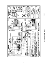
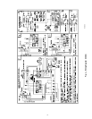
The control system depends on correct polarity of power supply.
Connect HOT wire (H) and NEUTRAL wire (N) as shown in Fig.
3or4.
A separate line voltage supply MUST be used with a fused
disconnect switch or circuit breaker between main power panel
and unit. (See Fig. 3 or 4.)
Metallic conduit (where required/used) may terminate at side panel
of unit. It is not necessary to extend conduit inside unit from side
panel to control box.
When replacing any original furnace wiring, use only 105°C No.
14 AWG copper wire.
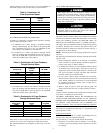
Table 7—Electrical Data
UNIT
SIZE
VOLTS—
HERTZ—
PHASE—
OPERATING
VOLTAGE RANGE
MAX
UNIT
AMPS
MIN
WIRE
GAGE
MAX WIRE
LENGTH (FT)
MAX FUSE OR
CKT BKR AMPS
Max.* Min.*
105-12 115—60—1 132 104 12.2 14 26 15
120-20 115—60—1 132 104 15.7 12 26 20
* Permissible limits of voltage range at which unit will operate satisfactorily.
† Length shown is as measured 1 way along wire path between unit and service panel for maximum 2 percent voltage drop.
‡ Time-delay fuse is recommended.
6