


35
CONTROLS
Sequence of Operation
The 50XT packaged heat pump is designed for installation with a
communicating UI. Thisunitwillnotrespondtocommandsprovided
by a common thermostat except under certain emergency situations.
The UI uses temperature, humidity and other data supplied from
indoorand outdoorsystem componentsto controlheating orcooling
system for optimum comfort.The unit will be commanded by the UI
to supply airflow. The unit will operate the indoor fan at requested
airflow for most modes.
The nominal requested airflow in high stage will be 350 cfm per ton
of nominal cooling capacity as defined by unit size. Actual airflow
request will be adjusted from nominal using indoor and outdoor
temperature and indoor humidity data to optimize the system
operation for occupant comfort and system efficiency. Refer to UI
literature for further system control details.
Airflow during electric heater operation must be greater than a
minimum level for safe operation. If UI instructs unit to turn on
electric heat and the requested airflow isless than the minimum level
the fan coil control will override requested value.
NOTE: Once the compressor has started and then has stopped, it
should notbe started again until 4 minuteshaveelapsed. Thecooling
cycle remains “on” until the room temperature drops to point that is
slightly below the cooling control s etting of the UI.
COOLING AND HEATING OPERATION
With a call for first stage cooling, the outdoor fan, reversing valve,
and low stage compressor are energized. If low --stage cannot
satisfy cooling demand, high--stage cooling is energized by the UI.
After second stage is satisfied, the unit returns to low--stage
operation until first stage is satisfied or until second stage is
required again. When both first stage and second stage cooling are
satisfied, the compressor will shut off. The reversing valve will
remain energized until the control board power is removed or a call
for heating is initiated. With a call for heating, the outdoor fan and
compressor are energized. The compressor will operate in high or
low stage operation, as needed, to meet the heating demand. When
the heating demand is satisfied, the compressor and fan will shut
off. The reversing valve is de-- energized in the heating mode.
NOTE: When two--stage unit is operating at low--stage, system
vapor (suction) pressure will be higher than a standard single--stage
system or high--stage operation.
NOTE: Outdoor fan motor will continue to operate for one
minute after compressor shuts off, when outdoor ambient is greater
than or equal to 100°F(38°C).
UTILITY INTERFACE WITH INFINITY CONTROL
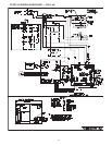
The utility curtailment relay should be connected to factory
supplied pigtails (PINK connected to R, VIOLET connected to Y2
on the control board) located in the low voltage splice box (see
Typical Wiring Schematic ). This input allows a power utility
device to interrupt compressor operation during peak load periods.
When the utility sends a signal to shut the system down, the UI will
display “Curtailment Active”.
Infinity Controlled Low Ambient Cooling
NOTE: When this unit is operating below 55_F (12.7°C) outdoor
temperature, provisions must be made for low ambient operation.
This unit is capable of low ambient cooling down to 0_F
(--17.7°C)ONLY when using the Infinity control. A low ambient kit
isnotrequired,andtheoutdoorfanmotordoesnotneedto bereplaced
forInfinity controlled low ambient operation. Low ambient cooling
must be enabled in the UI set--up. Fan may not begin to cycleuntil
about 40_F(4.4°C) OAT. Fan will cycle based on coil and outdoor
air temperature.