


4
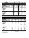
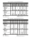
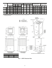
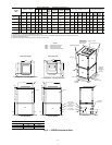
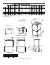
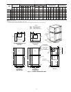
Table 1 — Physical Data — Aquazone™ 50RHC,RVC006-060 Units
LEGEND
*Size 006 available in 50RHC unit only.
†Size 041 available in 50RVC unit only.
NOTES:
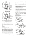
1. All units have grommet compressor mountings, and
1
/
2
and
3
/
4
-in.
electrical knockouts.
2. All sizes available as high-static units.
UNIT 50RHC,RVC 006* 009 012 018 024 030
COMPRESSOR (1 each) Rotary
Reciprocating
FACTORY REFRIGERANT CHARGE R-22
VERTICAL (oz)
—1414263837
FACTORY REFRIGERANT CHARGE R-22
HORIZONTAL (oz)
14 14 14 25 38 37
PSC FAN MOTOR AND BLOWER
Fan Motor Type/Speeds PSC/3 PSC/3 PSC/3 PSC/3 PSC/3 PSC/3
Fan Motor Std/High Static (Hp)
1
/
25
/—
1
/
10
/—
1
/
10
/—
1
/
8
/
1
/
6
1
/
4
/
3
/
4
3
/
4
/
3
/
4
Blower Wheel Size (D x W) (in.) Std/High Static 5 x 5/— 5 x 5/— 6 x 5/— 8 x 7/8 x 7 9 x 7/9 x 7 9 x 7/10 x 8
WATER CONNECTION SIZE (FPT)
1
/
2
1
/
2
1
/
2
1
/
2
3
/
4
3
/
4
VERTICAL
Air Coil
Dimensions (H x W) (in.) — 10 x 15 10 x 15 20 x 17.25 20 x 17.25 20 x 17.25
Total Face Area (ft
2
) — 1.04 1.04 2.4 2.4 2.4
Tube Size (in.) —
3
/
8
3
/
8
3
/
8
3
/
8
3
/
8
Fin Spacing (FPI) —1212121212
Number of Rows —23233
Filter Standard — 1-in. Throwaway — 10 x 18 10 x 18 1 — 20 x 20 1 — 20 x 20 1 — 20 x 20
Weight (lb)
Operating — 105 114 181 189 197
Packaged — 115 124 186 194 202
HORIZONTAL
Air Coil
Dimensions (H x W) (in.) 10 x 15 10 x 15 10 x 15 16 x 22 16 x 22 16 x 22
Total Face Area (ft
2
) 1.04 1.04 1.04 2.44 2.44 2.44
Tube Size (in.)
3
/
8
3
/
8
3
/
8
3
/
8
3
/
8
3
/
8
Fin Spacing (FPI) 12 12 12 12 12 12
Number of Rows 223233
Filter Standard — 1-in. Throwaway 10 x 18 10 x 18 10 x 18 1 — 16 x 25 1 — 16 x 25 1 — 16 x 25
Weight (lb)
Operating 103 105 114 181 189 197
Packaged 113 115 124 186 194 202
UNIT 50RHC,RVC 036 041† 042 048 060
COMPRESSOR (1 each) Reciprocating Scroll
FACTORY REFRIGERANT CHARGE R-22
VERTICAL (oz)
42 50 51 66 74
FACTORY REFRIGERANT CHARGE R-22
HORIZONTAL (oz)
41 50 51 66 74
PSC FAN MOTOR AND BLOWER
Fan Motor Type/Speeds PSC/3 PSC/3 PSC/3 PSC/3 PSC/3
Fan Motor Std/High Static (Hp)
1
/
2
/
3
/
4
3
/
4
/—
3
/
4
/
3
/
4
3
/
4
/1 1/1
Blower Wheel Size (D x W) (in.) Std/High Static 9 x 8/10 x 8 9 x 8/— 9 x 8/10 x 8 10 x 10/12 x 10 11 x 10/11 x 10
WATER CONNECTION SIZE (FPT)
3
/
4
3
/
4
3
/
4
11
VERTICAL
Air Coil
Dimensions (H x W) (in.) 24 x 21.25 1 — 20 x 17.25 24 x 21.25 24 x 28.25 20 x 28.25
Total Face Area (ft
2
) 3.62 2.4 3.62 4.71 4.71
Tube Size (in.)
3
/
8
3
/
8
3
/
8
3
/
8
3
/
8
Fin Spacing (FPI) 14 11 12 12 12
Number of Rows 2433 3
Filter Standard — 1-in. Throwaway 1 — 24 x 24 1 — 20 x 20 1 — 24 x 24
1 — 14 x 24
1 — 18 x 24
1 — 14 x 24
1 — 18 x 24
Weight (lb)
Operating 203 207 218 263 278
Packaged 209 212 224 270 285
HORIZONTAL
Air Coil
Dimensions (H x W) (in.) 20 x 25 — 20 x 25 20 x 35 20 x 35
Total Face Area (ft
2
) 3.47 — 3.47 4.86 4.86
Tube Size (in.)
3
/
8
—
3
/
8
3
/
8
3
/
8
Fin Spacing (FPI) 14 — 12 12 12
Number of Rows 2—3 3 3
Filter Standard — 1-in. Throwaway
1 — 20 x 28
2 — 20 x 14
—
1 — 20 x 28
2 — 20 x 14
1 — 20 x 24
1 — 20 x 14
1 — 20 x 24
1 — 20 x 14
Weight (lb)
Operating 203 — 218 263 278
Packaged 209 — 224 270 285
FPI — Fins per Inch
PSC — Permanent Split Capacitor