


2
Follow all safety codes. Wear safety glasses and work
gloves. Use quenching cloth for brazing operations. Have fire
extinguisher available. Read these instructions thoroughly and
follow all warnings or cautions attached to the unit. Consult
local building codes and the National Electrical Code (NEC)
for special installation requirements.
Understand the signal words — DANGER, WARNING,
and CAUTION. DANGER identifies the most serious hazards
which will result in severe personal injury or death. WARN-
ING signifies hazards that could result in personal injury or
death. CAUTION is used to identify unsafe practices, which
would result in minor personal injury or product and property
damage.
Recognize safety information. This is the safety-alert
symbol ( ). When you see this symbol on the unit and in
instructions or manuals, be alert to the potential for personal
injury.
GENERAL
This Installation and Start-Up Instructions literature is for
Aquazone™ water source heat pump systems.
Water source heat pumps (WSHPs) are single-package hori-
zontally and vertically mounted units with electronic controls
designed for year-round cooling and heating. Aquazone
WSHPs are available in the following unit configurations:
• RHC standard efficiency with horizontal airflow and
right, left or back discharge
• RHR high efficiency with horizontal airflow and right,
left or back discharge
• RHS premium efficiency with horizontal airflow and
right, left or back discharge
• RVC standard efficiency with vertical airflow and top
discharge
• RVR high efficiency with vertical airflow and top
discharge
• RVS premium efficiency with vertical airflow and top
discharge
• RDS premium efficiency with vertical airflow and bot-
tom discharge (downflow)
INSTALLATION
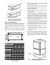
Step 1 — Check Jobsite —
Installation, operation and
maintenance instructions are provided with each unit. Before
unit start-up, read all manuals and become familiar with the
unit and its operation. Thoroughly check out the system before
operation. Complete the inspections and instructions listed
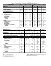
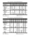
below to prepare a unit for installation. See Tables 1-3 for unit
physical data.
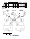
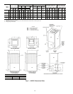
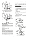
HORIZONTAL UNITS (50RHC,RHR,RHS) — Horizontal
units are designed for indoor installation only. Be sure to allow
adequate space around the unit for servicing. See Fig. 1-3 for
overall unit dimensions. Refer to Fig. 4 for an illustration of a
typical horizontal installation.
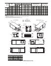
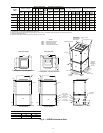
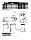
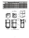
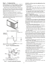
VERTICAL AND DOWNFLOW UNITS (50RVC,RVR,
RVS,RDS) — Vertical units are designed for indoor installa-
tions. While vertical units are typically installed in a floor-level
closet or a small mechanical room, the unit access guidelines
for these units are very similar to those described for horizontal
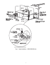
units. See Fig. 5-8 for overall dimensions. Refer to Fig. 9 for an
example of a typical vertical installation. Refer to Fig. 10 for a
sample downflow installation.
Step 2 — Check Unit — Upon receipt of shipment at
the jobsite, carefully check the shipment against the bill of
lading. Make sure all units have been received. Inspect the car-
ton or crating of each unit, and inspect each unit for damage.
Ensure the shipping company makes proper notation of any
shortages or damage on all copies of the freight bill. Concealed
damage not discovered during unloading must be reported to
the shipping company within 15 days of receipt of shipment.
NOTE: It is the responsibility of the purchaser to file all
necessary claims with the shipping company.
1. Verify unit is correct model for entering water tempera-
ture of job.
2. Be sure that the location chosen for unit installation pro-
vides ambient temperatures maintained above freezing.
Well water applications are especially susceptible to
freezing.
3. Be sure the installation location is isolated from sleeping
areas, private offices and other acoustically sensitive
spaces.
NOTE: A sound control accessory package may be used
to help eliminate sound in sensitive spaces.
4. Check local codes to be sure a secondary drain pan is not
required under the unit.
5. Be sure unit is mounted at a height sufficient to provide
an adequate slope of the condensate lines. If an appropri-
ate slope cannot be achieved, a field-supplied condensate
pump may be required.
6. Provide sufficient space for duct connection.
7. Provide adequate clearance for filter replacement and
drain pan cleaning. Do not allow piping, conduit, etc. to
block filter access.
8. Provide sufficient access to allow maintenance and
servicing of the fan and fan motor, compressor and coils.
Removal of the entire unit from the closet should not be
necessary.
9. Provide an unobstructed path to the unit within the closet
or mechanical room. Space should be sufficient to allow
removal of unit if necessary.
10. Provide ready access to water valves and fittings, and
screwdriver access to unit side panels, discharge collar,
and all electrical connections.
11. Where access to side panels is limited, pre-removal of the
control box side mounting screws may be necessary for
future servicing.
Electrical shock can cause personal injury or death. Before
installing or servicing system, always turn off main power
to system. There may be more than one disconnect switch.
Turn off accessory heater power if applicable.
IMPORTANT: The installation of water source heat pump
units and all associated components, parts, and accessories
which make up the installation shall be in accordance with
the regulations of ALL authorities having jurisdiction and
MUST conform to all applicable codes. It is the responsi-
bility of the installing contractor to determine and comply
with ALL applicable codes and regulations.
To avoid equipment damage, do not use these units as a
source of heating or cooling during the construction
process. The mechanical components and filters used in
these units quickly become clogged with construction
dirt and debris which may cause system damage.