


18
Step 8 — Field Power Supply Wiring
All field installed wiring, including the electrical ground,
MUST comply with the National Electrical Code (NEC) as
well as applicable local codes. In addition, all field wiring must
conform to the Class II temperature limitations described in the
NEC.
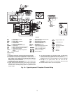
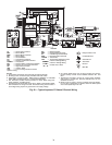
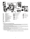
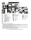
Refer to unit wiring diagrams Fig. 19-22 for a schematic of
the field connections, which must be made by the installing (or
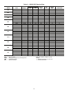
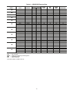
electrical) contractor. Refer to Tables 5-7 for fuse sizes.
Consult the unit wiring diagram located on the inside of the
compressor access panel to ensure proper electrical hookup.
The installing (or electrical) contractor must make the field
connections when using field-supplied disconnect.
Operating voltage must be the same voltage and phase as
shown in Electrical Data shown in Tables 5-7.
Make all final electrical connections with a length of flexi-
ble conduit to minimize vibration and sound transmission to
the building.
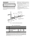
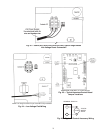
POWER CONNECTION — Make line voltage connection
by connecting the incoming line voltage wires to the L side
of the CC terminal as shown in Fig. 23. See Tables 5-7 for
correct wire and maximum overcurrent protection sizing.
SUPPLY VOLTAGE — Operating voltage to unit must be
within voltage range indicated on unit nameplate.
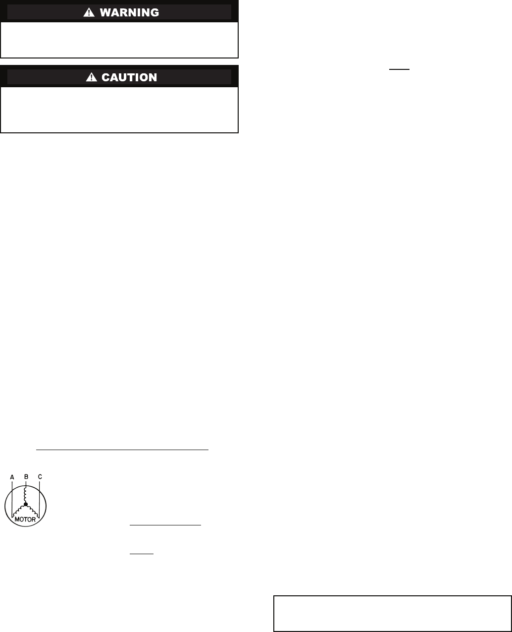
On 3-phase units, voltages under load between phases must
be balanced within 2%. Use the following formula to deter-
mine the percentage voltage imbalance:
% Voltage Imbalance
Example: Supply voltage is 460-3-60.
AB = 452 volts
BC = 464 volts
AC = 455 volts
Determine maximum deviation from average voltage:
(AB) 457 – 452 = 5 v
(BC) 464 – 457 = 7 v
(AC) 457 – 455 = 2 v
Maximum deviation is 7 v.
Determine percent voltage imbalance.
This amount of phase imbalance is satisfactory as it is
below the maximum allowable 2%.
Operation on improper line voltage or excessive phase
imbalance constitutes abuse and may cause damage to electri-
cal components.
NOTE: If more than 2% voltage imbalance is present, contact
your local electric utility.
208-VOLT OPERATION — All 208-230 volt units are factory
wired for 208 volts. The transformers may be switched to
230-volt operation by switching the red (208 volt) wire with
the orange (230 volt) wire at the L1 terminal.
Step 9 — Field Control Wiring
THERMOSTAT CONNECTIONS — The thermostat should
be wired directly to the Aquazone™ control board. See
Fig. 19-22, and 24.
WATER FREEZE PROTECTION — The Aquazone control
allows the field selection of source fluid freeze protection
points through jumpers. The factory setting of jumper JW3
(FP1) is set for water at 30 F. In earth loop applications, jumper
JW3 should be clipped to change the setting to 10 F when
using antifreeze in colder earth loop applications. See Fig. 25.
AIR COIL FREEZE PROTECTION — The air coil freeze
protection jumper JW2 (FP2) is factory set for 30 F and should
not need adjusting.
ACCESSORY CONNECTIONS — Terminal A on the control
is provided to control accessory devices such as water valves,
electronic air cleaners, humidifiers, etc. This signal operates
with the compressor terminal. See Fig. 26. Refer to the specific
unit wiring schematic for details.
NOTE: The A terminal should only be used with 24 volt
signals — not line voltage signals.
WATER SOLENOID VALVES — Water solenoid valves may
be used on primary secondary pump and ground water installa-
tions. A typical well water control valve wiring, which can
limit waste water in a lockout condition is shown in Fig. 26. A
slow closing valve may be required to prevent water hammer.
When using a slow closing valve, consider special wiring con-
ditions. The valve takes approximately 60 seconds to open
(very little water will flow before 45 seconds) and it activates
the compressor only after the valve is completely opened by
closing its end switch. When wired as shown, the valve will
have the following operating characteristics:
1. Remain open during a lockout
2. Draw approximately 25 to 35 VA through the “Y” signal
of the thermostat.
To avoid possible injury or death due to electrical shock,
open the power supply disconnect switch and secure it in
an open position during installation.
Use only copper conductors for field-installed electrical
wiring. Unit terminals are not designed to accept other
types of conductors. Failure to follow this safety precaution
could lead to equipment damage.
= 100 x
max voltage deviation from average voltage
average voltage
Average Voltage =
452 + 464 + 455
3
=
1371
3
= 457
% Voltage Imbalance = 100 x
7
457
= 1.53%
IMPORTANT: Connecting a water solenoid valve can
overheat the anticipators of electromechanical thermo-
stats. Only use relay based electronic thermostats.