


33
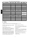
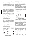
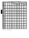
Table 9 – LEDs
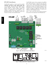
The LEDs on the RTU--MP show the status of certain functions
If this LED is on... Status is...
Power The RTU MP has power
Rx The RTU MP is receiving data fro m the network segment
Tx The RTU MP is transmitting data over the network segment
DO# The digital output is active
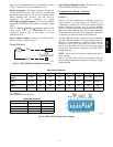
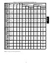
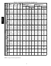
The Run and Error LEDs indicate control module and network status
If Run LED shows...
And Error LED shows... Status is...
2 flashes per second Off Normal
2 flashes per second
2flashes,
alternating with Run LED
Five minute auto---restart delay after system error
2 flashes per second
3flashes,
then off
Control module has just been formatted
2 flashes per second
4flashes,
then pause
Two or more devices on this network have the
same ARC156 network address
2 flashes per second On
Exec halted after frequent system errors o r
control programs halted
5 flashes per second On Exec start---up aborted, Boot is running
5 flashes per second Off Firmware transfer in progress, Boot is running
7 flashes per second
7 flashes per second, alternating with
Run LED
Ten second recovery period after brownout
14 flashes per second
14 flashes per second,
alternating with Run LED
Brownout
On On
Failure. Try the following solutions:
S Turn the RTU---MP off, then on.
S Format the RTU --- MP.
S Download memory to the RTU---MP.
S Replace the RTU---MP.
NOTE: Refer to Form 48--50H--T--2T for complete
configuration of RTU--MP, operating sequences and
troubleshooting information. Refer to RTU--MP 3rd Party
Integration Guide for details on configuration and
troubleshooting of connected networks. Have a copy of these
manuals available at unit start--up.
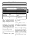
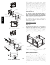
Smoke Detectors
Smoke detectors are available as factory--installed options on
50HCQ models. Smoke detectors may be specified for
Supply Air only or for Return Air without or with
economizer or in combination of Supply Air and Return Air.
Return Air smoke detectors are arranged for vertical return
configurations only. All components necessary for operation
are factory--provided and mounted. The unit is
factory--configured for immediate smoke detector shutdown
operation; additional wiring or modifications to unit terminal
board may be necessary to complete the unit and smoke
detector configuration to meet project requirements.
Units equipped with factory--optional Return Air smoke
detectors require a relocation of the sensor module at unit
installation. See “Completing Installation of Return Air
Smoke Sensor:” on page 35 for details.
System —
The smoke detector system consists of a four--wire
controller and one or two sensors. Its primary function is
to shut down the rooftop unit in order to prevent smoke
from circulating throughout the building. It is not to be
used as a life saving device.
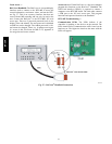
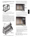
Controller —
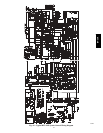
The controller (see Fig. 58) includes a controller housing,
a printed circuit board, and a clear plastic cover. The
controller can be connected to one or two compatible duct
smoke sensors. The clear plastic cover is secured to the
housing with a single captive screw for easy access to the
wiring terminals. The controller has three LEDs (for
Power, Trouble and Alarm) and a manual test/reset button
(on the cover face).
Sensor —
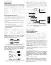
The sensor (see Fig. 59) includes a plastic housing, a
printed circuit board, a clear plastic cover, a sampling
tube inlet and an exhaust tube. The sampling tube (when
used) and exhaust tube are attached during installation.
The sampling tube varies in length depending on the size
of the rooftop unit. The clear plastic cover permits visual
inspections without having to disassemble the sensor. The
cover attaches to the sensor housing using four captive
screws and forms an airtight chamber around the sensing
electronics. Each sensor includes a harness with an RJ45
terminal for connecting to the controller. Each sensor has
four LEDs (for Power, Trouble, Alarm and Dirty) and a
manual test/reset button (on the left--side of the housing).
50HCQA