


10
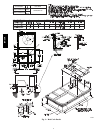
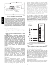
Economizer Hood and Two--Position Hood —
NOTE: If the power exhaust accessory is to be installed
on the unit, the hood shipped with the unit will not be
used and must be discarded. Save the aluminum filter for
use in the power exhaust hood assembly.
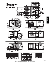
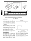
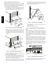
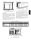
1. The indoor coil access panel will be used as the top of
the hood. Remove the screws along the sides and bot-
tom of the indoor coil access panel. See Fig. 10.
SIDE
PANEL
INDOOR
COIL
ACCESS
PANEL
INDOOR
COIL
ACCESS
PANEL
CAULK
HERE
TOP
SIDE
PANEL
C06025
Fig. 10 -- Indoor Coil Access Panel Relocation
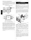
2. Swing out indoor coil access panel and insert the
hood sides under the panel (hood top). Use the screws
provided to attach the hood sides to the hood top. Use
screws provided to attach the hood sides to the unit.
See Fig. 11.
B
TOP
PANEL
INDOOR COIL
ACCESS PANEL
19 1/16”
SCREW
HOOD DIVIDER
LEFT
HOOD
SIDE
33 3/8”
(848mm)
(483mm)
C06026
Fig. 11 -- Economizer Hood Construction
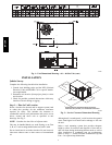
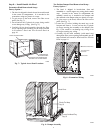
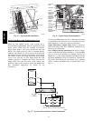
3. Remove the shipping tape holding the economizer ba-
rometric relief damper in place.
4. Insert the hood divider between the hood sides. See
Fig. 11 and 12. Secure hood divider with 2 screws on
each hood side. The hood divider is also used as the
bottom filter rack for the aluminum filter.
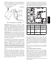
5. Open the filter clips which are located underneath the
hood top. Insert the aluminum filter into the bottom
filter rack (hood divider). Push the filter into position
past the open filter clips. Close the filter clips to lock
the filter into place. See Fig. 12.
DIVIDER
BAROMETRIC
RELIEF
CLEANABLE
ALUMINUM
FILTER
FILTER
HOOD
FILTER
CLIP
OUTSIDE
AIR
C08634
Fig. 12 -- Economizer Filter Installation
6. Caulk the ends of the joint between the unit top panel
and the hood top.
7. Replace the filter access panel.
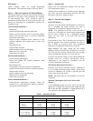
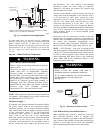
Step 9 — Install External Condensate Trap and
Line
The unit has one
3
/
4
-in. condensate drain connection on
the end of the condensate pan and an alternate connection
on the bottom. See Fig. 13. Unit airflow configuration
does not determine which drain connection to use. Either
drain connection can be used with vertical or horizontal
applications.
When using the standard side drain connection, ensure the
red plug in the alternate bottom connection is tight. Do
this before setting the unit in place. The red drain pan can
be tightened with a
1
/
2
--in. square socket drive extension.
To use the alternate bottom drain connection, remove the
red drain plug from the bottom connection (use a
1
/
2
-- i n .
square socket drive extension) and install it in the side
drain connection.
DRAIN
(FACTORY-INSTALLED)
PLUG
CONDENSATE PAN (SIDE VIEW)
STANDARD
SIDE DRAIN
ALTERNATE
BOTTOM DRAIN
C08021
Fig. 13 -- Condensate Drain Pan (Side View)
The piping for the condensate drain and external trap can
be completed after the unit is in place. See Fig. 14.
50HCQA