


15
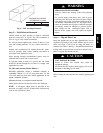
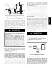
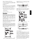
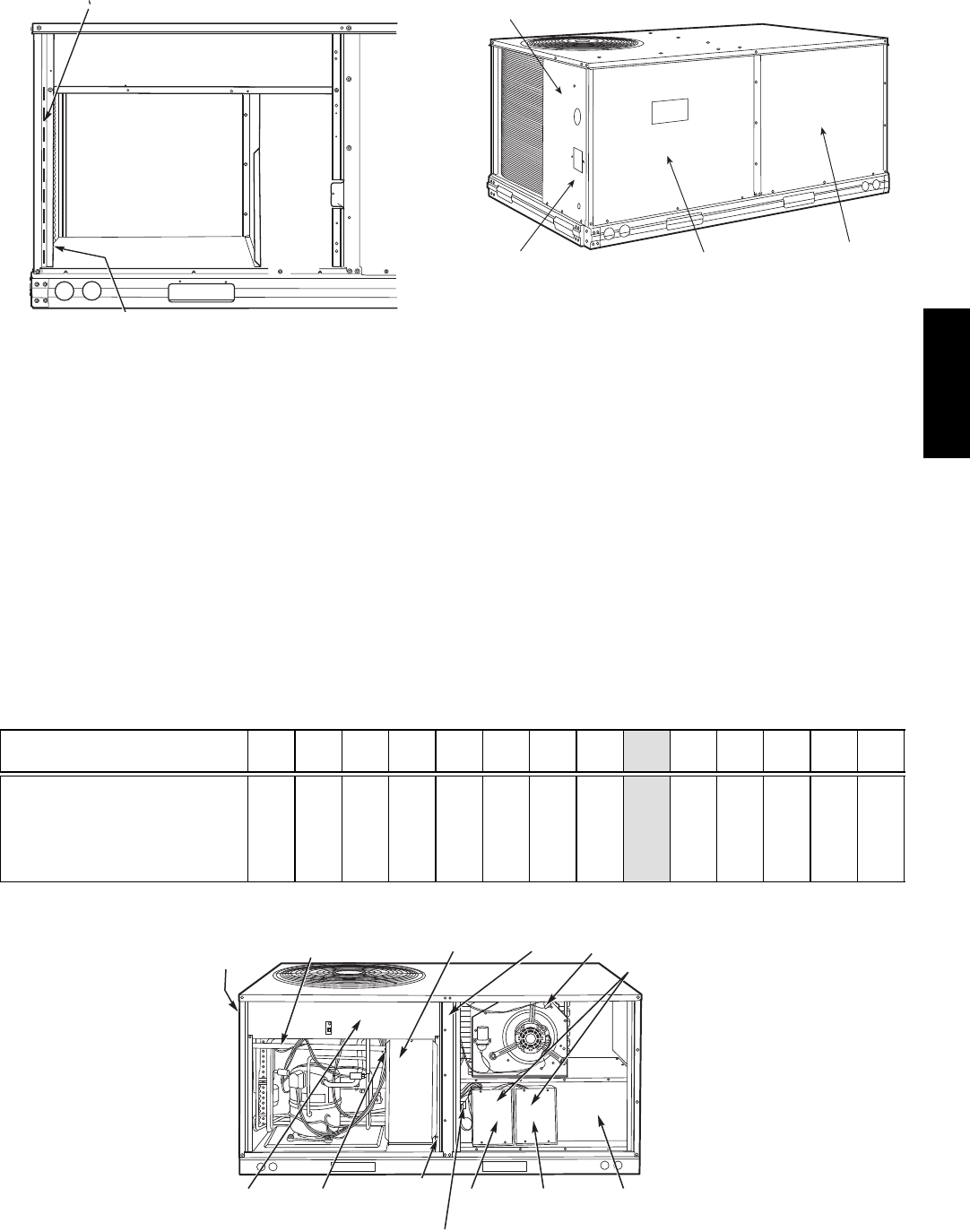
RACEWAY
HOLE IN END PANEL (HIDDEN)
C08027
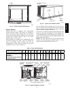
Fig. 22 -- Field Control Wiring Raceway
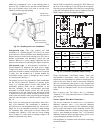
Electric Heaters
50HCQ units may be equipped with field--installed
accessory electric heaters. The heaters are modular in
design, with heater frames holding open coil resistance
wires strung through ceramic insulators, line--break limit
switches and a control contactor. One or two heater
modules may be used in a unit.
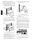
Heater modules are installed in the compartment below
the indoor (supply) fan outlet. Access is through the
indoor access panel. Heater modules slide into the
compartment on tracks along the bottom of the heater
opening. See Fig. 23, Fig. 24 and Fig. 25.
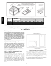
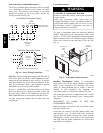
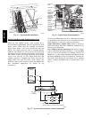
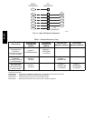
DISCONNECT MOUNTING
LOCATION
UNIT BLOCK-OFF
PANEL
OUTDOOR
ACCESS PANEL
INDOOR
ACCESS
PANEL
C08133
Fig. 23 -- Typical Access Panel Location
Not all available heater modules may be used in every
unit. Use only those heater modules that are UL listed for
use in a specific size unit. Refer to the label on the unit
cabinet for the list of approved heaters.
Unit heaters are marked with Heater Model Numbers. But
heaters are ordered as and shipped in cartons marked with
a corresponding heater Sales Package part number. See
Table 2 for correlation between heater Model Number and
Sales Package part number.
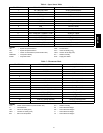
NOTE: The value in position 9 of the part number differs
between the sales package part number (value is 1 or 3)
and a bare heater model number (value is 0).
Table 2 – Heater Model Number
Bare Heater Model Number C R H E A T E R 0 0 1 A 0 0
Heater Sales Package PNO
Includes:
Bare Heater
Carton and packing materials
Installation sheet
C R H E A T E R 1 0 1 A 0 0
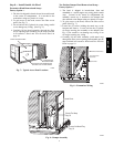
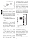
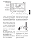
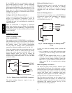
DISCONNECT
MOUNTING
LOCATION
EMT OR RIGID CONDUIT
(FIELD-SUPPLIED)
SINGLE
POINT BOX
CENTER
POST
HEATER
COVERS
HEATER
MOUNTING
BRACKET
HEATER
MODULE
(LOCATION 2)
HEATER
MODULE
(LOCATION 1)
SINGLE POINT
BOX
MOUNTING
SCREW
BRACKET AND
CONDUIT
DRIP BOOT
MAIN
CONTROL
BOX
CONTROL WIRE TERMINAL BLOCK
MANUAL RESET
LIMIT SWITCH
C08134
Fig. 24 -- Typical Component Location
50HCQA