


12
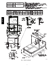
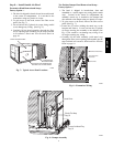
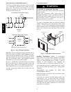
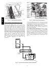
Units with Factory--Installed Disconnect —
The factory--installed option disconnect switch is located
in a weatherproof enclosure located under the main
control box. The manual switch handle is accessible
through an opening in the access panel. Discard the
factory test leads (see Fig. 16).
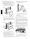
Units Without Disconnect Option
Units With Disconnect Option
2
4
6
1
3
5
L1
L2
L3
Optional
Disconnect
Switch
Disconnect factory test leads; discard.
Factory
Wiring
11 13 13
L1
L2 L3
TB
C
IFC
(3 Phase
Indoor Motor)
(1 Phase Indoor Motor
and 3 Phase Unit)
208/230-3-60
460-3-60
575-3-60
Disconnect
per
NEC
11 23
C
208/230-1-60
Disconnect
per
NEC
C10241
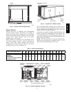
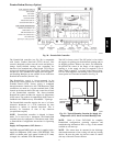
Fig. 16 -- Power Wiring Connections
All Units: All field wiring must comply with NEC and all
local codes. Size wire based on MCA (Minimum Circuit
Amps) on the unit informative plate. See Fig. 16 and the
unit label diagram for power wiring connections to the
unit power terminal blocks and equipment ground.
Maximum wire size is #2 ga AWG per pole.
Provide a ground--fault and short--circuit over--current
protection device (fuse or breaker) per NEC Article 440
(or local codes). Refer to unit informative data plate for
MOCP (Maximum Over--current Protection) device size.
All field wiring must comply with the NEC and local
requirements.
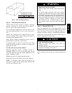
Convenience Outlets —
ELECTRICAL OPERATION HAZARD
Failure to follow this warning could result in personal
injury or death.
Units with convenience outlet circuits may use
multiple disconnects. Check convenience outlet for
power status before opening unit for service. Locate
its disconnect switch, if appropriate, and open it.
Tag--out this switch, if necessary.
!
WARNING
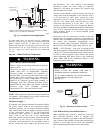
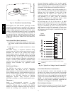
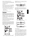
Two types of convenience outlets are offered on 50HCQA
models: Non--powered and unit--powered. Both types
provide a 125--volt GFCI (ground--fault circuit--interrupter)
duplex receptacle rated at 15--A behind a hinged waterproof
access cover, located on the end panel of the unit. See
Fig. 17.
Convenience
Outlet
GFCI
Pwd-CO
Fuse
Switch
Pwd-CO
Transformer
Control Box
Access Panel
C08128
Fig. 17 -- Convenience Outlet Location
Installing Weatherproof Cover: A weatherproof
while-in-use cover for the factory-installed convenience
outlets is now required by UL standards. This cover
cannot be factory-mounted due its depth; it must be
installed at unit installation. For shipment, the
convenience outlet is covered with a blank cover plate.
The weatherproof cover kit is shipped in the unit’s control
box. The kit includes the hinged cover, a backing plate
and gasket.
DISCONNECT ALL POWER TO UNIT AND
CONVENIENCE OUTLET.
Remove the blank cover plate at the convenience outlet;
discard the blank cover.
Loosen the two screws at the GFCI duplex outlet, until
approximately
1
/
2
-in (13 mm) under screw heads are
exposed. Press the gasket over the screw heads. Slip the
backing plate over the screw heads at the keyhole slots
and align with the gasket; tighten the two screws until
snug (do not over-tighten).
50HCQA