


to a level which causes the Thermidistat™ to close its contacts.
When the contacts close, the airflow will return to 100 percent
of selected cooling airflow. To activate this mode wire in
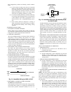
Thermidistat™ see jumper in Fig. 10.
e. DEHUMIDIFY AND SUPER DEHUMIDIFY
CAPABILITIES
This model unit is capable of responding to a signal from
Thermidistat™ to operate in comfort control modes such as
Super Dehumidify Mode. Consult literature provided with
Thermidistat™ to determine if these operating modes are
available, and to see control set up instructions. No special
setup or wiring of unit is required.
48JZ SEQUENCE OF OPERATION
a. CONTINUOUS FAN
(1.) Thermostat closes circuit R to G—The Blower runs at
continuous fan airflow
b. COOLING MODE
(1.) If indoor temperature is above temperature set point and
humidity is below humidity set point, thermostat closes
circuits R to G, R to Y/Y2 and R to O—The unit delivers
single speed cooling airflow.
c. COOLING MODE-DEHUMIDIFICATION
(1.) If indoor temperature is above temperature set point and
humidity is above humidity set point, Thermidistat™
closes circuits R to G, R to Y/Y2, R to O and Thermidis-
tat™ opens R to DH—The unit delivers airflow which is
approximately 80 percent of the nominal cooling airflow to
increase the latent capacity of the system.
d. COOLING MODE-SUPER DEHUMIDIFY OPERATION
(SEE QUICK REFERENCE GUIDE)
NOTE: Thermidistat™ is capable of providing Super Dehu-
midify operation mode and must be configured as outlined in its
installation instructions. Consult indoor control literature to deter-
mine if control is capable of providing Super Dehumidify inputs
and for configuration instruction.
(1.) If the indoor temperature is below the temperature set
point and the humidity is above the humidity set point, the
Thermidistat™ closes circuit R to O, opens circuits R to
DH and R to G, and closes circuit R to Y/Y2. If circuit R
to G is closed (24-v.), the motor will deliver airflow at the
full cooling or cooling plus dehumidify mode requested
value. If circuit R to G is open (0–v.) for super dehumidify
mode, the motor delivers reduced airflow to maximize the
humidity removal of the system while minimizing over
cooling.
e. GAS HEATING MODE
(Occurs if outdoor temperature is below outdoor temperature
change over setpoint.)
(1.) Thermostat closes circuit R to W/W1—The unit delivers
the selected gas heat airflow. The IGC will control 45 sec.
on delay with no airflow and 45 sec. off delay.
f. HEAT PUMP HEATING MODE
(Occurs if outdoor temperature is above outdoor temperature
change over setpoint.)
(1.) Thermidistat™ closes circuit R to G and R to Y/Y2–The
unit delivers selected heat pump heating airflow.
g. HEATING MODE—SUPER COMFORT HEAT OPERA-
TION
NOTE: The Thermidistat™ is capable of providing Super Com-
fort Heat operation mode and must be configured as outlined in its
installation instructions. The system must be installed with appro-
priate outdoor temperature sensor. Consult Thermidistat™ litera-
ture for configuration instructions. Consult sensor instructions for
sensor installation details.
If the outdoor temperature is in the range of 12° to 40° F, the
Thermidistat™ closes circuit R to Y/Y2 and opens circuit R to G.
If circuit R to G is closed (24-v.), the motor will deliver airflow at
the full heating requested value. If circuit R to G is open (0-v.) for
maximum heating comfort, the motor delivers reduced airflow to
maximize the temperature and minimize the draft effect of the
heated air leaving the unit.
EASY SELECT™—50GL & 50JZ
EASY SELECT™ CONFIGURATION TAPS FOR 50GL &
50JZ
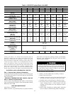
Easy Select™ taps are used by the installer to configure a system.
The ICM motor uses the selected taps to modify its operation to a
pre-programmed table of airflows.
The unit must be configured to operate properly with system
components with which it is installed. To successfully configure a
basic system (see information printed on circuit board label located
next to select pins), move the 6 select wires to the pins which
match the components used.
a. AUX HEAT kW/CFM—SELECT HEATER RANGE FOR
SIZE OF ELECTRIC HEATER INSTALLED
Installer must select the auxiliary heat airflow approved for
application with kW size heater installed. If no heater is
installed, this step can be skipped. Each select pin is marked
with a range of heaters for which airflow (also marked), is
approved. For increased comfort, select the narrowest kW range
matching the heater size, for example, 0–10 for 10–kW heater.
This airflow must be greater than the minimum for CFM for
electric heater application with the size system installed for safe
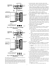
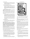
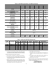
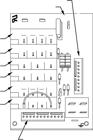
Fig. 11—Detail of SPP Printed-Circuit Board
C01033
EASY SELECT
HEATER/MOTOR
AUX HEAT KW/CFM
0-30
1075
SEC1 SEC2
J1
AC/HP SIZE
036 030 024 018
AC
HP-COMFORT
HP-EFF
NOM HI
ENH
LO
SYSTEM TYPE
AC/HP CFM ADJUST
ON/OFF DELAY
CONTINUOUS FAN
MED HI YELLO
AUX1 HUM1
AUX2
24VAC
GRY
HUM2
YEL
WHT
BLK
ORN
BLU
VIO
0-20
875
0-10
725
0
90
30
90
0
0
0-5
625
TM
J2
D
H
R
W
1
W
2
Y
1
Y/Y
2
G
O
C
9 PIN CONNECTOR
ICM PRINTED CIRCUIT BOARD
12 PIN CONNECTOR
A
B
C
D
E
F
7