


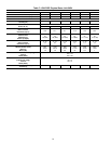
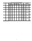
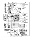
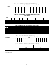

ICM QUICK REFERENCE GUIDE
c01034
EASY SELECT
HEATER/MOTOR
AUX HEAT KW/CFM
0-30
1075
SEC1 SEC2
J1
AC/HP SIZE
036 030 024 018
AC
HP-COMFORT
HP-EFF
NOM HI
ENH
LO
SYSTEM TYPE
AC/HP CFM ADJUST
ON/OFF DELAY
CONTINUOUS FAN
MED HI YELLO
AUX1 HUM1
AUX2
24VAC
GRY
HUM2
YEL
WHT
BLK
ORN
BLU
VIO
0-20
875
0-10
725
0
90
30
90
0
0
0-5
625
TM
J2
D
H
R
W
1
W
2
Y
1
Y/Y
2
G
O
C
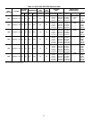
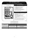
QUICK REFERENCE GUIDE
SET-UP INSTRUCTIONS FOR WARMER HEATING TEMPERATURES
AND SUPER HUMIDITY CONTROL IN COOLING
A. AUX HEAT - Set for heater size (Ex: 0-10 for 10 kw)
B. AC/HP SIZE - Set for size of outdoor unit
C. SYSTEM TYPE - Select "HP COMFORT"
D. AC/HP CFM ADJUST - Select "LO"
E. ON/OFF DELAY - Select "ENH"
F. CONTINUOUS FAN - Select desired speed
2. Remove Jumper J1 to activate all dehumidify modes.
3. Complete wiring and install outdoor temperature sensor
according to Installation Instructions.
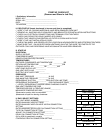
1. Configuration Taps
(See Installation Instructions, for detailed description.)
• Option 5 (Variable Speed Motors) - set to ON
• Option 7 (Super Dehumidify) - set to ON
• Option 12 (Heaters during Defrost) - setting "2" is
suggested for all heaters
• Option 16 - Heat pump systems set to ON for warmer heat
below 40° F.
• Option 17 - Select programmable or non-programmable mode.
2. Thermidistat Control Configurations
(See Thermidistat™ Control Installation Instructions for
detailed description.)
3. Set desired humidity level on front of Thermidistat
(50 to 55% RH recommended). For dehumidification in
cooling, both "dhu" and "cool" must be displayed.
1. Set "DIP Switches" - Set the dip switches (back of Thermidistat
Control Board) appropriately for specific system being installed.
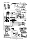
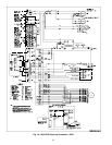
EASY SELECT BOARD
THERMIDISTAT™ CONTROL SETTINGS
9 PIN CONNECTOR
ICM PRINTED CIRCUIT BOARD
12 PIN CONNECTOR
A
B
C
D
E
F
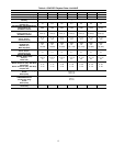
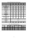
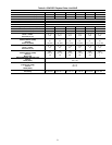
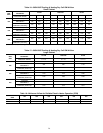
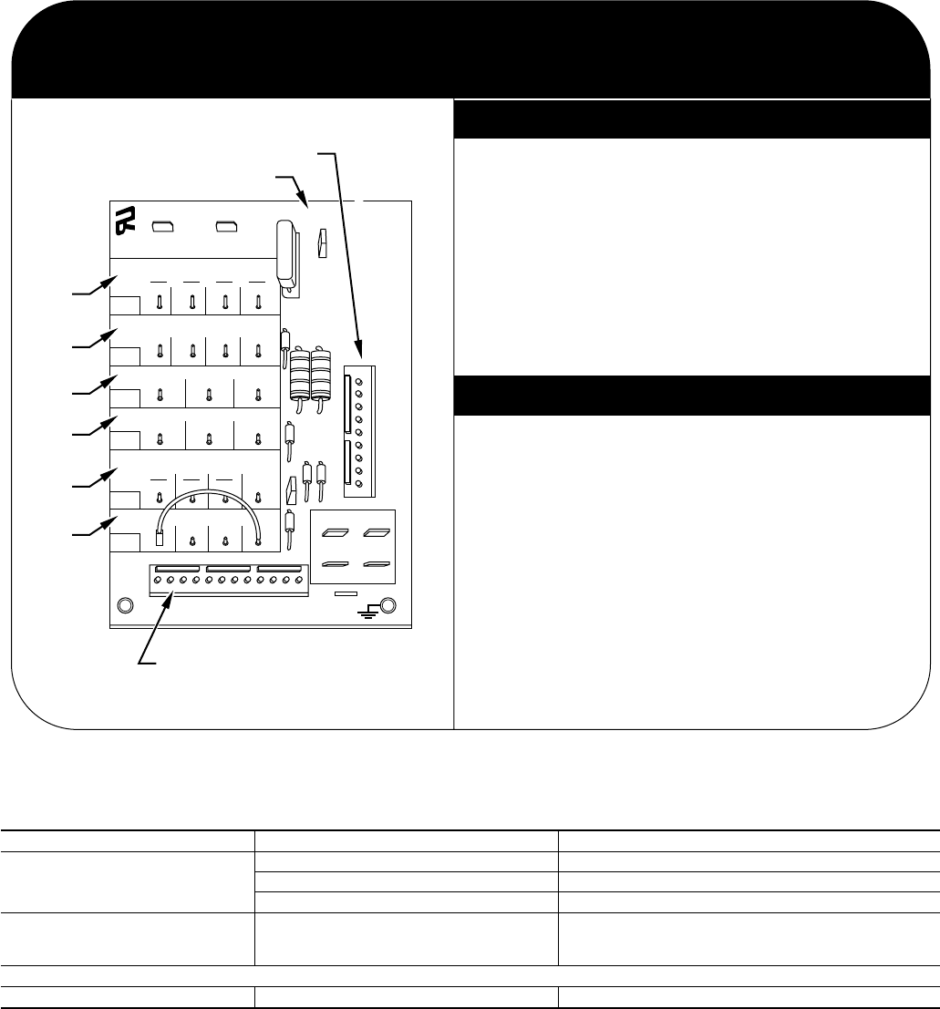
Table 24—Troubleshooting Chart
SYSTEM CAUSE REMEDY
IFM does not run
Blower wheel not secured to shaft Inspect and properly tighten blower wheel to shaft
Insufficient voltage at motor Determine cause and correct
Power connectors not properly seated Connectors should snap easily; do not force
IFM operation is intermittent Connectors not firmly seated
Gently pull wires individually
to be sure they are inserted
into the connectors
28