


f. Loosen set-screw that secures wheel to motor shaft, remove
screws that secure motor mount brackets to blower housing,
and slide motor and motor mount out of blower housing.
2. Remove and clean blower wheel as follows:
a. Ensure proper reassembly by marking wheel orientation.
b. Lift wheel from housing. When handling and/or cleaning
blower wheel, be sure not to disturb balance weights (clips)
on blower wheel vanes.
c. Remove caked-on dirt from wheel and housing with a
brush. Remove lint and/or dirt accumulations from wheel
and housing with vacuum cleaner, using soft brush attach-
ment. Remove grease and oil with mild solvent.
d. Reassemble wheel into housing.
e. Reassemble motor into housing. Be sure set-screw(s) are
tightened on motor shaft flats and not on round part of
shaft.
f. Pivot blower access panel back into place. Adjust wire
assemblies so that wiring follows proper pathways.
g. Reinstall unit access panel.
3. Restore electrical power, then gas supply to unit. Start unit and
check for proper blower rotation and motor speeds during
heating and cooling cycles.
TROUBLESHOOTING
START-UP CHECKLIST
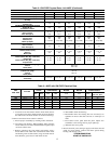
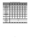
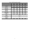
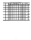
Table 2—ICM FIOP Physical Data—Unit 48GP (Continued)
THIS DATA APPLIES TO 48GP UNITS WITH THE ICM INDOOR MOTOR FIOP
UNIT SIZE 48GP 048090 048115 048130 060090 060115 060130
NOMINAL CAPACITY (ton) 444555
OPERATING WEIGHT (lb.) 421 421 421 468 468 468
COMPRESSORS
Quantity
Scroll
1
REFRIGERANT (R-410A)
Quantity (lb.)
9.5 9.5 9.5 10.0 10.0 10.0
REFRIGERANT METERING DEVICE
Orifice ID (in.)
AccuRater™ Piston
.073 .073 .073 .086 .086 .086
CONDENSER COIL
Rows...Fins/in.
Face Area (sq ft)
2...17
12.3
2...17
12.3
2...17
12.3
2...17
16.4
2...17
16.4
2...17
16.4
CONDENSER FAN
Nominal Cfm
Diameter (in.)
Motor Hp (Rpm)
3300
22
1/4 (1100)
3300
22
1/4 (1100)
3300
22
1/4 (1100)
3300
22
1/4 (1100)
3300
22
1/4 (1100)
3300
22
1/4 (1100)
EVAPORATOR COIL
Rows...Fins/in.
Face Area (sq ft)
4...15
4.7
4...15
4.7
4...15
4.7
4...15
4.7
4...15
4.7
4...15
4.7
EVAPORATOR BLOWER
Nominal Airflow (Cfm)
Size (in.)
Motor (HP)
1600
11X10
3/4
1600
11X10
3/4
1600
11X10
3/4
2000
11X10
1.0
2000
11X10
1.0
2000
11X10
1.0
FURNACE SECTION*
Burner Orifice No. (Qty...Drill Size)
Natural Gas
Burner Orifice No. (Qty...Drill Size)
Propane Gas
3...38
3...46
3...33
3...42
3...31
3...41
3...38
3...46
3...33
3...42
3...31
3...41
HIGH-PRESSURE SWITCH (psig)
Cutout
Reset (Auto)
610±15
420±25
LOSS-OF-CHARGE/LOW-PRESSURE SWITCH
(Liquid Line) (psig)
Cutout
Reset (Auto)
20±5
45±10
RETURN-AIR FILTERS (in.)
Throwaway
24X30X1 24X30X1 24X30X1 24X30X1 24X30X1 24X30X1
* Based on altitude of 0 to 2000 ft.
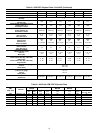
Table 3—48GP with ICM FIOP Electrical Data
UNIT
SIZE 48GP
V-PH-HZ
VOLTAGE
RANGE
COMPRESSOR
OUTDOOR FAN
MOTOR
INDOOR FAN
MOTOR
POWER SUPPLY
MIN MAX RLA LRA FLA FLA MCA
MAX FUSE
OR CKT. BKR.
024 208/230–1–60 187 253 13.5 61.0 0.9 4.3 22.1 30
030 208/230–1–60 187 253 14.7 73.0 0.9 4.3 23.6 30
036 208/230–1–60 187 253 15.4 83.0 0.9 6.8 27.0 35
042 208/230–1–60 187 253 18.6 105.0 0.9 6.8 31.0 40
048 208/230–1–60 187 253 20.5 109.0 1.6 6.8 34.0 40
060 208/230–1–60 187 253 27.6 158.0 1.6 9.2 45.2 60
13