


9
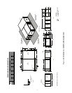
Condensing section must be located in same plane as, or
above, evaporator section to maintain the liquid refrigerant seal
at the expansion device. This permits expansion device to feed
liquid refrigerant to evaporator coil properly. To split sections
(some of the following steps may be eliminated depending on
particular application):
1. Disconnect all electrical power to unit.
2. Remove the 10 size 10 drive screws that hold on the top
tie strap.
3. Remove the 8 size
3
/
8
-in. drive bolts that hold on each
side angle.
4. Control panel access panels are held on with 2 size 10
drive screws for each panel. A standard 50AH024-060
unit has one control panel located in the evaporator sec-
tion. A standard 50AH072 or 096 unit has a control panel
in both the evaporator and condenser sections.
5. Units have resealable fittings. Do not cut refrigerant pip-
ing. See Interconnecting Refrigerant Tubing section be-
low for procedure on installing tubing.
6. Install evaporator and condensing sections in desired
locations.
7. Use sufficient length of refrigerant piping to reconnect
piping cut in previous step. Refer to Carrier System
Design Manual, Part 3, for additional piping data.
8. Recharge unit with R-410A. See Refrigerant Charge sec-
tion on page 18 for more information.
After splitting sections, additional refrigerant must be added
to system to ensure proper refrigerant charge. The amount of
refrigerant to be added depends on length of tubing added to
system and operating temperatures of system. Refer to Carrier
System Design Manual, Chapter 3. Allow unit to operate at
least 10 minutes before adjusting refrigerant charge.
Since standard roomtop unit has negligible line losses, split-
ting the system can increase line loss and decrease system
capacity. Capacity reduction can be determined by referring to
Carrier System Design Manual.
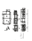
INTERCONNECTING REFRIGERANT TUBING — The
interconnecting tubing kit comes with all factory-optional split-
table units. After the separated sections have been installed, the
interconnecting tubing can be run, using the self-sealing cou-
plings supplied in the interconnect tubing kit (see Fig. 7 and 8).
For dual circuits, 2 kits are supplied. It is recommended that
some refrigerant oil be placed on the coupling threads to facili-
tate threading.
Perform the following procedure:
1. For condensing section, hand thread the female halves of
the self-sealing couplings (supplied with the interconnect
tubing kit) onto the male couplings (factory supplied and
installed on the condensing section). Turn union nut ap-
proximately 1 to 1
1
/
2
turns. This is to make sure that the
interconnecting tubing will be routed and brazed with the
self-sealing couplings in their final proper location, so
that there will be no difficulty when the final coupling as-
sembly is made.
2. For evaporator section, hand thread the male halves of the
self-sealing couplings (supplied with the interconnect
tubing kit) onto the female couplings (factory supplied
and installed on the evaporating section). Turn union nut
approximately 1 to 1
1
/
2
turns. This is to make sure that the
interconnecting tubing will be routed and brazed with the
self-sealing couplings in their final proper location, so
that there will be no difficulty when the final coupling as-
sembly is made.
3. Run the interconnecting tubing required.
NOTE: Installations may be made with up to 50 ft equiv-
alent line lengths by installing the recommended tube siz-
es and adding the necessary refrigerant. For equivalent
line lengths greater than 50 ft, contact Carrier for line siz-
ing and additional accesories required.
4. The interconnect tubing kit contains a sufficient number
of Schrader access valves to permit installation of one in
each end of both the liquid and suction lines of the field-
supplied tubing. Each interconnecting line (suction, liq-
uid, hot gas) must have one of the supplied Schrader ac-
cess fittings installed into the field-supplied tubing, how-
ever, for short lengths of tubing, only one Schrader in
each line is necessary. Install the Schrader valve fittings
into the tubing before brazing the couplings onto the ends
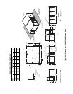
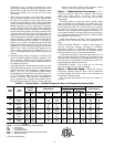
SELF-SEALING
COUPLING
(FEMALE HALF)
SELF-SEALING
COUPLING
(MALE HALF)
SELF-SEALING
FLANGE
SCREWS
Fig. 7 — Self Sealing Coupling
a50-8551
IMPORTANT: On units with more than one refrig-
erant circuit, be careful not to intermix lines of the
various circuits. If the connections were labeled
before disconnecting the couplings, this should not
be a problem. Half couplings may be removed to
make brazing to the interconnecting tubing more
convenient.
CAUTION
When brazing tubing to the self-sealing couplings, be sure
to use a wet rag, running water bath or chill blocks on the
quick-connects to prevent overheating the valves and dam-
aging the seals
.
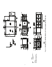
EVAPORATOR
SECTION
A
A
C
C
C
C
D
D
D
D
B
B
A
A
CONDENSING
SECTION
A — Male self-sealing fittings
B — Refrigerant piping between sections
C — Female self-sealing fittings
D — Schrader fittings
Fig. 8 — Tubing Installation
a50-8552