


8
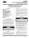
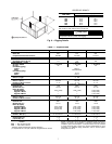
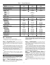
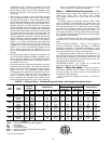
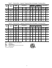
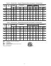
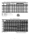
Table 1 — Physical Data (cont)
LEGEND
*Shipping weights include base unit plus packaging.
†If components are to be split, additional refrigerant will be needed.
NOTE: If components are to be split, the maximum length of refrigerant
tubing to be used is 50 equivalent ft, assuming components will be
installed in same horizontal plane. If components are not to be installed
in same horizontal plane, contact your Carrier representative for more
information. For additional piping information, refer to Carrier System
Design Manual, Part 3.
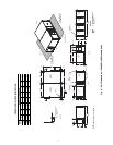
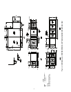
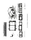
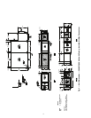
Step 4 — Rig and Place Unit — Move and store unit
in horizontal position. Provide space around unit for service,
filter access, ductwork, and overhead clearance as indicated in
Fig. 2-5.
Using suitable hydraulic lift source, raise unit up to meet
bottom of the 8 threaded rods suspended from ceiling (12 rods
for units with air-side economizer). Center unit so that the 8 or
12 threaded rods can be easily inserted into the factory-drilled
holes at each end. Refer to Fig. 6 for rigging details.
Apply washers and locknuts on ends of each of the 8 or 12
rods.
Tighten locknuts sufficiently so that unit weight is support-
ed entirely by the 8 or 12 rods. Level unit within the space by
adjusting locknuts.
NOTE: For split systems, 8 (or 12) suspension rods are
required (4 for each section and 4 for economizer if required).
Refer to Splitting Systems section below.
Step 5 — Make Condensate Piping Connec-
tions —
One
7
/
8
-in. OD pipe thread condensate drain con-
nection is provided for the evaporator section.
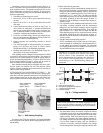
Step 6 — Install Ductwork — Use flexible ductwork
to attach duct to unit and to help control transmission of vibra-
tions to building structures. Attach ductwork to the return and
supply ends of both coils.
If unit is located with condenser close to outside of building,
install a field-supplied rainhood. Hood intake dimensions
should be same as condenser return-air dimensions. In addi-
tion, install a triple-layer bird screen over rainhood intake to
eliminate possibility of insects, birds, water, or debris from
entering unit. Ensure hood and/or louvers are installed correct-
ly to avoid condenser air recirculation.
Step 7 — Split Systems (Factory Option, if
Required) — The Roomtop
®
50AH units may be split into
2 sections, if desired, with condensing section mounted
remotely horizontally. The unit must be ordered with the
“Splittable” cabinet type as shown in the unit model number
nomenclature. See Fig. 1. All splittable units come with the
interconnecting tubing kit.
Sections installed in the same horizontal plane may be sepa-
rated by up to 50 equivalent ft of tubing. Use type L copper or
better.
UNIT 50AH 060 072 096
OPERATING WEIGHT (lb)
Base Unit 960 1214 1283
Evaporator/Condenser Sections 421/519 554/634 556/701
SHIPPING WEIGHT (lb)* 1093 1647 1716
REFRIGERANT TYPE R-410A
Operating Charge (lb-oz)† 8-8 6-6 6-6
COMPRESSOR — TYPE Scroll
Quantity...Model 1...ZPKP51K5E 2...ZP31K5E 2...ZP38K5E
Oil (oz) 42 25 42
HPS Setting (psig)
Cutout 650 ± 7
Reset Manual Reset
LPS Setting (psig)
Cutout 75 ± 7
Reset 100 ± 7
CONDENSATE DRAIN CONNECTION
Size (in.)...Type
7
/
8
...OD
CONDENSER COIL Copper Tubes — Aluminum Fins
Size (L x H) (in.) 90 x 30 40 x 30 (2 coils) 40 x 30 (2 coils)
Number of Rows...Fins/in. 2...12 2...20 2...20
CONDENSER FAN Centrifugal — Belt Drive
Nominal Cfm 3000 5200 6400
Blower Size (in.) 15 x 15 18 x 18 18 x 18
Motor Hp (Rpm)
Standard Motor 0.33 (1725) 1.00 (1725)
1.50 (1725)
Upgrade 1 Motor 0.50 (1725) 1.50 (1725)
2.00 (1725)
Upgrade 2 Motor 0.75 (1725) —
3.00 (1725)
EVAPORATOR COIL Copper Tubes — Aluminum Fins
Size (L x H) (in.) 32 x 26 46 x 28 46 x 28
Number of Rows...Fins/in. 3...14 3...14 3...14
EVAPORATOR AIR FAN Centrifugal — Belt Drive
Nominal Cfm 2000 2400 3200
Blower Size (in.) 12 x 9 15 x 15 15 x 15
Motor Hp (Rpm)
Standard Motor 0.33 (1725) 0.50 (1725)
0.75 (1725)
Upgrade 1 Motor 0.50 (1725) 0.75 (1725)
1.00 (1725)
Upgrade 2 Motor 0.75 (1725) 1.00 (1725)
1.50 (1725)
Upgrade 3 Motor 1.00 (1725) 1.50 (1725)
2.00 (1725)
INDOOR-AIR FILTERS Factory-Supplied Disposable Type
Number...Size (in.) 2...18 x 24 x 1 2...20 x 25 x 1 2...20 x 25 x 1
INTERCONNECTING TUBING SIZE
Suction (Qty...in.) 1...
7
/
8
1...
5
/
8
1...
7
/
8
Liquid (Qty...in.)
1...
3
/
8
1...
3
/
8
1...
7
/
8
HPS — High-Pressure Switch
LPS — Low-Pressure Switch
IMPORTANT: Unit must be level to operate properly.