


7
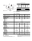
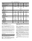
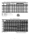
Table 1 — Physical Data
LEGEND
*Shipping weights include base unit plus packaging.
†If components are to be split, additional refrigerant will be needed.
NOTE: If components are to be split, the maximum length of refrigerant
tubing to be used is 50 equivalent ft, assuming components will be
installed in same horizontal plane. If components are not to be installed
in same horizontal plane, contact your Carrier representative for more
information. For additional piping information, refer to Carrier System
Design Manual, Part 3.
UNIT 50AH 024 036 048
OPERATING WEIGHT (lb)
Base Unit 903 910 952
Evaporator/Condenser Sections 399/484401/489 417/515
SHIPPING WEIGHT (lb)* 1036 1043 1085
REFRIGERANT TYPE R-410A
Operating Charge (lb-oz)† 4-5 4-5 8-8
COMPRESSOR — TYPE Scroll
Quantity...Model 1...ZP20K5E 1...ZP31K5E 1...ZP38K5E
Oil (oz) 25 25 42
HPS Setting (psig)
Cutout 650 ± 7
Reset Manual Reset
LPS Setting (psig)
Cutout 75 ± 7
Reset 100 ± 7
CONDENSATE DRAIN CONNECTION
Size (in.)...Type
7
/
8
...OD
CONDENSER COIL Copper Tubes — Aluminum Fins
Size (L x H) (in.) 40 x 30 40 x 30 90 x 30
Number of Rows...Fins/in. 4...14 4...14 2...12
CONDENSER FAN Centrifugal — Belt Drive
Nominal Cfm 1700 2000 2500
Blower Size (in.) 15 x15 15 x 15 15 x 15
Motor Hp (Rpm)
Standard Motor 0.33 (1725) 0.33 (1725)
0.33 (1725)
Upgrade 1 Motor ——
0.50 (1725)
Upgrade 2 Motor ——
0.75 (1725)
EVAPORATOR COIL Copper Tubes — Aluminum Fins
Size (L x H) (in.) 32 x 16 32 x 16 32 x 26
Number of Rows...Fins/in. 3...12 3...12 3...14
EVAPORATOR AIR FAN Centrifugal — Belt Drive
Nominal Cfm 800 1200 1600
Blower Size (in.) 12 x 9 12 x 9 12 x 9
Motor Hp (Rpm)
Standard Motor 0.25 (1725) 0.33 (1725)
0.33 (1725)
Upgrade 1 Motor 0.33 (1725) 0.50 (1725)
0.50 (1725)
Upgrade 2 Motor 0.50 (1725) 0.75 (1725)
0.75 (1725)
Upgrade 3 Motor — 1.00 (1725)
1.00 (1725)
INDOOR-AIR FILTERS Factory-Supplied Disposable Type
Number...Size (in.) 2...18 x 24 x 1 2...18 x 24 x 1 2...18 x 24 x 1
INTERCONNECTING TUBING SIZE
Suction (Qty...in.) 1...
5
/
8
1...
5
/
8
1...
7
/
8
Liquid (Qty...in.)
1...
3
/
8
1...
3
/
8
1...
3
/
8
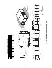
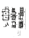
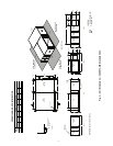
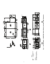
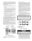
Fig. 6 — Rigging Details
CENTER OF GRAVITY
NOTE: Fasten threaded rods through holes in end frames as shown.
Use 4 rods on each side of unit for a total of 8.
UNIT 50AH
DIMENSIONS (in.)
AB
024 29.0 25.6
036 28.8 26.0
048 29.0 27.0
060 28.8 26.8
072 59.3 31.2
096 60.0 31.5
CAUTION
All panels must be in place when rigging.
HPS — High-Pressure Switch
LPS — Low-Pressure Switch