


18
Blower Belt Adjustment — Inspect blower belt for
wear, proper belt tension, and pulley alignment as conditions
require or at the beginning of each heating and air conditioning
season.
Make sure that fan shafts and motor shafts are parallel and
level. The most common causes of misalignment are nonparal-
lel shafts and improperly located sheaves. Where shafts are not
parallel, belts on one side are drawn tighter and pull more than
their share of the load. As a result, these belts wear out faster,
requiring the entire set to be replaced before it has given maxi-
mum service. If misalignment is in the sheave, belts enter and
leave the grooves at an angle, causing excessive belt and
sheave wear.
SHAFT ALIGNMENT — Check shaft alignment by measur-
ing the distance between the shafts at 3 or more locations. If the
distances are equal, then the shafts are parallel.
SHEAVE ALIGNMENT
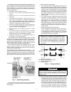
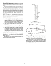
1. To check the location of the fixed sheaves on the shafts,
use a straightedge or a piece of string. If the sheaves are
properly aligned, the string will touch them at the points
indicated by the arrows in Fig. 9. Rotate each sheave a
half revolution to determine whether the sheave is wob-
bly or the drive shaft is bent. Correct any misalignment.
2. With sheaves aligned, tighten cap screws evenly and
progressively.
NOTE: There should be a
1
/
8
-in. to
1
/
4
-in. gap between
the mating part hub and the bushing flange. If the gap is
closed, the bushing is probably the wrong size.
3. With taper-lock bushed hubs, be sure the bushing bolts
are tightened evenly to prevent side-to-side pulley wob-
ble. Check by rotating sheaves and rechecking sheave
alignment. When substituting field-supplied sheaves for
factory-supplied sheaves, only the motor sheave should
be changed.
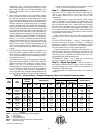
BELT TENSION ADJUSTMENT — Using a gage, apply
4 lb of force to the center of the belt and adjust the tension until
a deflection of
1
/
64
-in. is achieved for every inch of shaft center
distance. See Fig. 10.
Ideal belt tension is the lowest value under which belt slip
will not occur at peak load conditions.
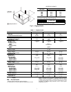
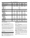
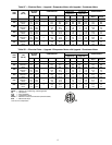
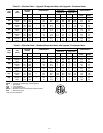
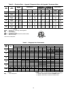
Refrigerant Charge — Unit is shipped fully charged.
Amount of refrigerant charge is listed on unit nameplate (also
refer to Table 1). Refer to Carrier GTAC II; Module 5; Charg-
ing, Recovery, Recycling, and Reclamation manual.
Unit panels must be in place when unit is operating during
charging procedure. Unit must operate for at least 10 minutes
before adjusting charge. Use standard evacuating techniques.
After evacuating system, weigh in the specified amount of re-
frigerant. (Refer to Table 1.)
Fig. 9 — Sheave Alignment
a50-7135tf
BELT SPAN
LB FORCE
DEFLECTION
Fig. 10 — Fan Belt Tension
a50-7136ef