


17
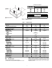
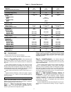
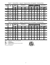
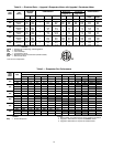
Table 4 — Condenser-Fan Performance
LEGEND NOTES:
1. Refer to Table 1 for condenser fan motor and drive information.
2. Upgrade 1 Static Motor is required for boldface values.
3. Upgrade 2 Static Motor is required for shaded values.
START-UP
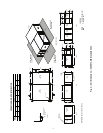
Unit Preparation —
Make sure unit has been installed in
accordance with installation instructions and applicable codes.
Compressor Mounting — Compressors are internally
mounted on rubber-in-shear (RIS) isolators. Do not loosen or
remove compressor holddown bolts.
Internal Wiring — Check all electrical connections in
unit control boxes and tighten as required.
Refrigerant Service Valves — Each unit system has
2 Schrader-type service ports, one on the suction line and one
on the compressor discharge line. Be sure that caps on the ports
are tight.
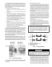
Compressor Rotation — On 50AH036-096, 3-phase
units, it is important to be certain compressor is rotating in the
proper direction. To determine whether or not compressor is
rotating in the proper direction:
1. Connect service gages to suction and discharge pressure
fittings.
2. Energize the compressor.
3. The suction pressure should drop and the discharge pres-
sure should rise, as is normal on any start-up.
If the suction pressure does not drop and the discharge pres-
sure does not rise to normal levels:
1. Note that the condenser and evaporator fans may also be
rotating in the wrong direction.
2. Turn off power to the unit and tag disconnect.
3. Reverse any two of the unit power leads.
4. Reapply power to the unit; remove tag.
5. Verify correct refrigerant pressures.
The suction and discharge pressure levels should move to
their normal start-up levels.
NOTE: When the compressor is rotating in the wrong direc-
tion, the unit will sound louder than normal and will not
provide cooling.
Cooling — To start unit, turn on main power supply. Set
system selector switch at COOL position and fan switch at
AUTO. position. Adjust thermostat to a setting below room
temperature. Compressor, condenser and evaporator motors
start on closure of contactors.
TO SHUT OFF UNIT — Set system selector switch at OFF
position or reset thermostat at a position above room
temperature.
SERVICE
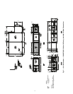
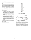
Filters —
Filters are disposable and should be inspected and
replaced at regular intervals monthly or as conditions require.
They are located in front of the evaporator coil and may be re-
moved by sliding them horizontally out to edge of unit. See
Fig. 2-5. No tools are required for installation or removal of
filters.
Condenser Coil — The condenser coil is accessible
through the side access panel on condenser section, or through
side access panel on condenser section. Use a stiff brush when
cleaning coil. Be careful not to bend aluminum fins.
Evaporator Coil — The evaporator coil is accessible for
cleaning through the side access panel on evaporator section.
When necessary, wash coil with a commercial cleaner (Oakite
164) or dishwasher detergent using a pressurized spray canis-
ter. Flush coil from return-air duct side and take care not to get
water in ductwork or unit insulation.
Condensate Drain — Clean and empty drain pan at
least once a year to prevent sludge build-up.
Lubrication — Lubrication of the condenser and evapora-
tor motors is not necessary since both are equipped with
permanently lubricated bearings. Do not oil.
Unit Condenser Motor — All 50AH units contain
belt-driven adjustable-pulley fan systems. The unit fan motors
are shipped with adjustable pulley at 4 turns open.
Blower Wheel Servicing — In-space servicing is rec-
ommended for the evaporator and condenser blowers. Both are
removed by loosening and removing the 2 screws (sizes 024-
060) or 4 screws (sizes 072 and 096) that hold them in place. In
both cases, the entire assembly is then moved outside of the
base unit. Once outside, the blower wheel and condenser shaft
bearings and/or evaporator motor can be serviced.
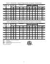
UNIT
SIZE
50AH
CFM
EXTERNAL STATIC PRESSURE (in. wg)
0.0 0.1 0.2 0.3 0.4 0.5
RpmBhpRpmBhpRpmBhpRpmBhpRpmBhpRpmBhp
024 1700 247 0.07 255 0.07 262 0.08 269 0.08 277 0.08 2840.09
036 2000 276 0.11 2820.11289 0.12 295 0.12 301 0.12 307 0.13
048 2500 251 0.17 305 0.18 357 0.22 408 0.27 456 0.32
501 0.37
060 3000 287 0.22 334 0.28 378 0.33 421 0.38
464 0.43 505 0.49
072 5200 367 0.68 438 0.89 464 0.98 490 1.07 516 1.16 542 1.25
096 6400 448 1.26 524 1.59 546 1.70
568 1.81————
Bhp — Brake Horsepower
WARNING
Disconnect all power to the unit before performing mainte-
nance or service. Electrical shock and personal injury could
result.
IMPORTANT: If repairs to refrigerant cycle compo-
nents (e.g., compressor, filter drier, etc.) are required,
recover all refrigerant from the system by using both
high and low-pressure ports. Then remove base unit
from the space.