


10
of the tubing. Use a
1
/
4
-in. hole to mount the valve. Clean
and debur the tubing before doing any brazing to ensure
that no chips or debris are left in the refrigerant circuit.
Remove the Schrader valve cap and core before doing
any brazing.
5. After brazing the tubing to the self-sealing coupling
halves, evacuate each line to 500 microns. Check to make
sure that each line holds a vacuum after removal of the
vacuum pump (indicating no leaks). Add the appropriate
charge of R-410A refrigerant using the Schrader valves.
Refasten male halves to outer back panel of evaporator
section with flanges and screws (if they were removed for
brazing to tubing). Wipe off coupling seals and threaded
surfaces with a clean cloth to prevent the inclusion of dirt
or foreign material into the system. Lubricate rubber seal
and metal seal in the male halves with refrigeration oil.
Thread coupling halves together by hand to ensure proper
mating of threads. Continue to handthread each half-cou-
pling to its mating half until resistance is felt (approxi-
mately 1
1
/
2
to 1
3
/
4
turns). Complete the connection of the
mating half-couplings with a wrench. The suction line
couplings (size 12) will be totally engaged after an addi-
tional 5
1
/
2
to 5
3
/
4
turns. The liquid line couplings (size 8)
will be totally engaged after an additional 4
1
/
2
to 4
3
/
4
turns. Use a backup wrench to prevent the couplings from
twisting.
6. Refrigerant piping must be insulated in accordance with
local codes and/or applicable ASHRAE standards. Insu-
lation exposed to weather must be suitable for outdoor
use. Provide protection from water and shielding from so-
lar radiation as necessary.
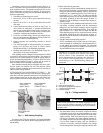
7. Add refrigerant to the system to compensate for the addi-
tional interconnecting tubing. The suction line should be
pitched downward to the compressor, sloping approxi-
mately
1
/
4
-in. every 10 ft to facilitate oil return. P-traps
(field supplied) are required for all suction line risers ev-
ery 15 ft. When the evaporator is above the condensing
section, an inverted P-trap should be incorporated as
close as possible to the evaporator (this minimizes flood-
back/oil slugging during the off cycle). If the condensing
section is more than 50 ft above the evaporator, consult
Carrier for specific refrigeration components.
Step 8 — Make Electrical Connections — Con-
nect power wiring to junction box located on unit side near
control box access panel. All wiring must comply
with National Electrical Code (NEC) and all local code
requirements.
Operating voltage to compressor must be within voltage
range as indicated on unit nameplate. On 3-phase units, volt-
ages between phases must be balanced within 2% and current
must be balanced within 10%. Contact local power company
for correction of improper voltage or phase imbalance. Unit
failure as a result of operation on improper line voltage or ex-
cessive phase imbalance constitutes abuse and may cause dam-
age to electrical components. Such operation would invalidate
any applicable Carrier warranty.
Install a fused disconnect per NEC. Refer to unit nameplate
and Tables 2A-2L for fuse sizes and wire amperages for all
units.
FIELD CONTROL WIRING — Install a Carrier-approved
accessory thermostat assembly according to installation
instructions provided by thermostat manufacturer. Locate
thermostat assembly on a solid wall in the conditioned space
away from drafts to sense average room temperature.
Using thermostat cable or equivalent single leads of no. 18
AWG (American Wire Gage) colored wire, route cable or wire
from the subbase terminals, up and through connector on unit
side (below power lead junction box) and connect to low-volt-
age terminal block inside the control box.
THERMOSTAT WIRE — Use 18 gage for 0 to 50-ft long
wires and 16 gage for 51 to 75-ft wire lengths.
Step 9 — Adjust Fan Speed — Adjust fan speed to
meet jobsite conditions. Refer to Tables 3 and 4 to determine
fan speed settings. See Service section of this document for
instructions to adjust fan speed.
The evaporator and condenser fan motors on all units are
belt drive.
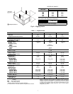
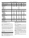
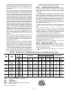
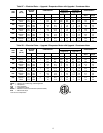
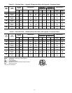
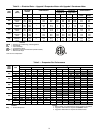
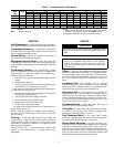
Table 2A — Electrical Data — Standard Evaporator Motor with Standard Condenser Motor
LEGEND
UNIT
50AH
V-PH
(60 Hz)
VOLTAGE
RANGE
COMPRESSOR
FAN MOTORS
POWER SUPPLY
Evaporator
(Standard)
Condenser
(Standard)
Min Max QTY RLA LRA Hp FLA Hp FLA
Min Ckt
Amps
MOCP
Amps
024 208/230-1 187 254 1 13.5 58.0
1
/
4
1.25
1
/
3
1.7 19.8 35
036
208/230-1 187 254
1
16.7 79.0
1
/
3
1.7
1
/
3
1.7 24.3 40
208/230-3 187 254 10.4 73.0
1
/
3
1.3
1
/
3
1.3 15.6 25
460-3 414 508 5.8 38.0
1
/
3
0.7
1
/
3
0.7 8.6 15
048
208/230-1 187 254
1
19.9 109.0
1
/
3
1.7
1
/
3
1.7 28.3 50
208/230-3 187 254 13.6 83.1
1
/
3
1.3
1
/
3
1.3 19.6 35
460-3 414 508 6.1 41.0
1
/
3
0.7
1
/
3
0.7 8.9 15
060
208/230-1 187 254
1
26.4 134
1
/
3
1.7
1
/
3
1.7 36.4 65
208/230-3 187 254 16.0 110.0
1
/
3
1.3
1
/
3
1.3 22.6 40
460-3 414 508 7.8 52.0
1
/
3
0.7
1
/
3
0.7 11.1 20
072*
208/230-1 187 254
2
16.7 79.0
1
/
2
2.5 1 4.2 44.3 60
208/230-3 187 254 10.4 73.0
1
/
2
1.8 13.228.4 40
460-3 414 508 5.8 38.0
1
/
2
0.9 1 1.6 15.6 20
096*
208/230-1 187 254
2
19.9 109.0
3
/
4
3.2 1
1
/
2
6.5 54.5 75
208/230-3 187 254 13.6 83.1
3
/
4
2.4 1
1
/
2
4.8 37.8 50
460-3 414 508 6.1 41.0
3
/
4
1.2 1
1
/
2
2.4 17.3 25
HACR — Heating, Air Conditioning, and Refrigeration
Hp — Horsepower
FLA — Full Load Amps
LRA — Locked Rotor Amps
MOCP — Maximum Overcurrent Protection (HACR breaker)
RLA — Rated Load Amps
*Unit has two compressors.