


9
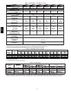
Table 1 – Physical Data -- Unit 48VT-- A
UNIT SIZE 024040 024060 030040 030060 036060 036090 042060 042090
NOMINAL CAPACITY ---ton 2 2 2--- 1/2 2---1/2 3 3 3--- 1/2 3--- 1/2
SHIPPING WEIGHT ---lb.
(kg)
368
167
368
167
378
171
378
171
450
204
450
204
491
223
491
223
COMPRESSORS Scroll
Quantity 1
REFRIGERANT (R---410A)
Quantity ---lb
(kg)
9.5
4.3
9.5
4.3
10.5
4.8
10.5
4.8
9.0
4.1
9.0
4.1
14.0
6.4
14.0
6.4
REFRIGERANT METERING
DEVICE
Indoor---TXV, Outdoor---Accurater
OUTDOOR ORIFICE
in. (qty)
(mm)
0.032 (2)
.81
0.032 (2)
.81
0.038 (2)
.97
0.038 (2)
.97
0.040(2)
1.02
0.040(2)
1.02
0.038(LeftODCoil)
0.040(RightODCoil)
.97/1.02
OUTDOOR COIL
Rows...Fins/in.
Face Area ---sq ft
2...21
13.6
2...21
13.6
2...21
15.4
2...21
15.4
2...21
13.6
2...21
13.6
2...21
19.4
2...21
19.4
OUTDOOR FAN
Nominal Cfm
Diameter---in.
(mm)
Motor Hp (Rpm)
2500
22
559
1/8(825)
2500
22
559
1/8(825)
2600
22
559
1/8(825)
2600
22
559
1/8(825)
3000
22
559
1/4(1100)
3000
22
559
1/4(1100)
3500
22
559
1/8(825)
3500
22
559
1/8(825)
INDOOR COIL
Rows...Fins/in.
Face Area ---sq ft
3...17
3.7
3...17
3.7
3...17
3.7
3...17
3.7
3...17
4.7
3...17
4.7
3...17
4.7
3...17
4.7
INDOOR BLOWER
Nominal Cooling Airflow---(CFM)
Size--- in.
(mm)
Motor --- hp
800
10x10
254x254
1/2
800
10x10
254x254
1/2
1000
10x10
254x254
1/2
1000
10x10
254x254
1/2
1200
11x10
279x254
3/4
1200
11x10
279x254
3/4
1400
11x10
279x254
3/4
1400
11x10
279x254
3/4
FURNACE SECTION*
Burner Orifice
NaturalGas Qty...DrillSize
PropaneGasQty...Drill Size
2...44
2...55
2...38
2...53
2...44
2...55
2...44
2...53
2...38
2...53
3...38
3...53
2...38
2...53
3...38
3...53
HIGH---PRESSURE SWITCH
(psig) Cut --- out
Reset (Auto)
650+/---15
420+/---25
LOSS--- OF--- CHARGE /
LOW---PRESSURE SWITCH
(Liquid Line) (psig)
Cut ---out
Reset (auto)
20 +/--- 5
45+/---10
RETURN---AIR FIL TERS † }
Throwaway (in.)
(mm)
20x20x1
508x508x25
20x24x1
508x610x25
24x30x1
610x762x25
*Based on altitude of 0to 2000 ft (0---610 m).
{Required filter sizes shown are based on the larger of the ARI (Air Conditioning and Refrigeration Institute) rated cooling airflow or the heating airflow velocity of
300 ft/minute for high---capacity type. Air filter pressure drop for non---standard filters must not exceed 0.08 IN. W.C.
} If using accessory filter rack refer to filterrack installation instructions forcorrectfiltersizeand quantity.
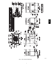
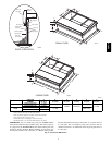
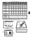
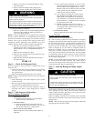
Horizontal Duct Covers
A09076
Basepan
Downflow
(Vertical)
Supply
Knockout
Basepan
Downflow
(Vertical)
Return
Knockout
A09077
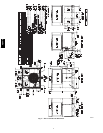
Fig. 8 -- Supply and Return Duct Opening
1
2
2
1
3
3
4
4
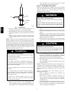
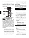
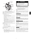
1. Score groove in corner 1 in both directions as far as you can reach.
2. Starting in corner 1, tap-out all sides with a small hammer. Be careful
not to damage any other part of unit.
3. If side from corner 3 to 4 is not accessible due to heat exchanger,
pivot panel up and down by hand until remaining side breaks off.
INSTRUCTIONS FOR REMOVING DOWNSHOT PANELS
A09054
Fig. 9 -- Vertical (Downflow) Discharge Duct Knockouts
48VT--A