


17
ELECTRICAL SHOCK HAZARD
Failure to follow this warning could result in personal
injury or death.
Before making any indoor wiring adjustments, shut off gas
supply. Then disconnect electrical power to the unit and
install lockout tag before changing blower speed.
!
WARNING
This unit has independent fan speeds for gas heating and cooling.
In addition, this unit has the field-selectable capability to run two
different cooling fan speeds: A normal cooling fan speed (350~400
CFM/Ton) and an enhanced dehumidification fan speed (As low as
320 CFM/Ton) for use with either a dehumidistat or a thermostat
that supports dehumidification.
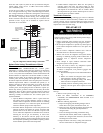
This unit is factory-set up for use with a single cooling fan speed.
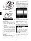
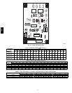
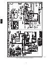
The cooling speed is marked “LOW” on the interface fan board
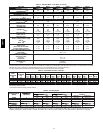
(IFB) (Fig. 14) . The factory-shipped settings are noted in Table
10. There are 3 additional speed tap wires available for use in
either gas heating or cooling (For color coding on the indoor fan
motor leads, see Table 6). The additional 3 speed tap wires are
shipped loose with vinyl caps and are located in the control box,
near the interface fan board (IFB) (Fig. 14).
Gas Heating Fan Speed Set-up
To change the gas heating speed:
1. Remove the vinyl cap off of the desired speed tap wire
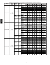
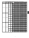
(Refer to Table 6 for color coding). Table 10 shows the
temperature rise associated with each fan speed for a given
static pressure. Make sure that the speed chosen delivers a
temperature rise within the rise range listed on the unit
rating plate.
2. Remove the current speed tap wire from the “GAS HEAT”
terminal on the interface fan board (IFB) (Fig.14) and place
vinyl cap over the connector on the wire.
3. Connect the desired speed tap wire to the “GAS HEAT”
terminal on the interface fan board (IFB).
Single Cooling Fan Speed Set-up (Dehumidification
feature not
used)
To change cooling speed:
1. Remove the vinyl cap off of the desired speed tap wire
(Refer to Table 6 for color coding). Add the wet coil
pressure drop in Table 8 to the system s tatic to determine the
correct cooling airflow speed in Table 10 that will deliver
the nominal cooling airflow as listed in T able 1 for each
size.
2. Remove the current speed tap wire from the “LOW”
terminal on the interface fan board (IFB) (Fig. 14) and place
vinyl cap over the connector on the wire.
3. Connect the desired speed tap wire to the “LOW” terminal
on the interface fan board (IFB).
Two Cooling Fan Speeds Set-up (Dehumidification
feature
used)
IMPORTANT: Dehumidification control must open control
circuit on humidity rise above set point.
Use of the dehumidification cooling fan speed requires use of
either a 24 VAC dehumidistat or a thermostat which includes
control of a 24 VAC dehumidistat connection. In either case, the
dehumidification control must open the control circuit on humidity
rise above the dehumidification set point. Dehumidification
controls are available with the reverse logic; these must not be
used.
1. Remove fan speed tap wire from the “LOW” terminal on
the interface fan board (IFB) (Fig. 14).
2. Determine correct normal cooling fan speed for unit and
application. Add the wet coil pressure drop in Table 8 to
the system static to determine the correct cooling airflow
speed in Ta ble 10 that will deliver the nominal cooling
airflow as listed in Table 1 for each size.
3. Remove the vinyl cap off of the desired speed tap wire
(Refer to Table 6 for color coding) for the normal cooling
fan speed and place desired speed tap wire on “HIGH” on
the interface board.
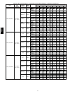
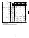
4. Refer to airflow tables (Table 10) to determine allowable
speeds for the dehumidification cooling fan speed. In Table
10, speeds that are not allowed for dehumidification cooling
are shaded.
5. Remove the vinyl cap off of the desired speed tap wire
(Refer to Table 6 for color coding) for the dehumidification
cooling fan speed and place desired speed tap wire on the
“LOW” connection on the interface board (IFB). Verify
that static pressure is in the acceptable range for the speed
tap to be used for dehumidification cooling.
6. Use any spare vinyl plugs to cap any unused speed tap
wires.
NOTE: For heat pump operation, the recommended airflow is 350
to 450 CFM for each 12,000 Btuh of rated cooling capacity.
Continuous Fan Operation
When the DEHUM feature is not used, the continuous fan speed
will be the same as cooling fan speed. When the DEHUM feature
is used, the continuous fan will operate on IFB “LOW” speed
when the DH c ontrol l ead is not ener gized, or IFB “HIGH” speed
when the DH lead is ener gized (see Fig. 14).
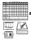
Table 6 – Color Coding for Indoor Fan Motor Leads
Black = Hi gh Speed
Orange =Med---High Speed
Red=MedSpeed
Pink = Med---Low Speed
Blue = Low Speed
48VT--A