


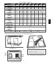
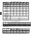

7
3. Attach a clevis of sufficient strength in the middle of the
straps. Adjust the clevis location to ensure unit is lifted level
with the ground.
After t he unit is placed on the roof curb or mounting pad, remove
the top skid.
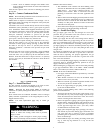
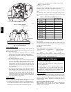
Step 6 — Connect Condensate Drain
NOTE: When installing condensate drain connection be sure to
comply with local codes and restrictions.
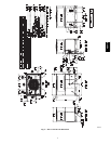
Model 48VT--A disposes of condensate water through a 3/4 in.
NPT fitting which exits through the compressor access panel (See
Fig. 2 and 3 for location).
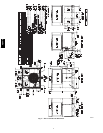
Condensate water can be drained directly onto the roof in rooftop
installations (where permitted) or onto a gravel apron in ground
level installations. Install a field--supplied condensate trap at end
of condensate connection to ensure proper drainage. Make sure that
the outlet of the trap is at least 1 in. (25 mm) lower than the
drain-- pan condensate connection to prevent the pan from
overflowing (See Fig. 6). Prime the trap with water . When us ing a
gravel apron, make sure it slopes away from the unit.
If the installation requires draining the condensate water away
from the unit, install a 2--in. (51 mm) trap at the condensate
connection to ensure proper drainage (See Fig. 6). Make sure that
the outlet of the trap is at least 1 in. (25 mm) lower than the
drain-- pan condensate connection. This prevents the pan from
overflowing.
Prime the trap with water. Connect a drain tube -- using a minimum
of 3/4 --in. PVC or 3/4 --in. copper pipe (all field--supplied) -- at the
outlet end of the 2-- in. (51 mm) trap. Do not undersize the tube.
Pitch the drain tube downward at a slope of at least 1--in. (25 mm)
for every 10 ft (3 m) of horizontal run. Be sure to check the drain
tube for leaks.
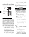
TRAP
OUTLET
1-in. (25 mm) min.
2-in. (51 mm) min.
A09052
Fig. 6 -- Condensate Trap
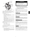
Step 7 — Install Flue Hood
The flue assembly is secured and shipped in the return air duct.
Remove duct cover to locate the assembly (See Fig. 8).
NOTE: Dedicated low NOx models MUST be installed in
California Air Quality Management Districts where a Low NOx
rule exists.
These models meet the California maximum oxides of nitrogen
(NOx) emissions requirements of 40 nanograms/joule or less as
shipped from the factory.
NOTE: Low NOx requirements apply only to natural gas
installations.
CARBON MONOXIDE POISONING HAZARD
Failure to follow this warning could result in personal
injury or death.
The venting system is designed to ensure proper venting.
The flue hood assembly must be installed as indicted in this
section of the unit i nstallation instructions.
!
WARNING
Install the flue hood as follows:
1. This installation must conform with local building codes
and with the National Fuel Gas Code (NFGC) NFPA 54 /
ANSI Z223.1, (in Canada, CAN/CGA B149.1, and
B149.2) latest revision. Refer to Provincial and local
plumbing or wastewater codes and other applicable local
codes.
2. Remove flue hood from shipping location (inside the return
section of the blower compartment--see Fig. 8). Remove the
return duct cover to locate the flue hood. Place flue hood
assembly over flue panel. Orient screw holes in flue hood
with holes in the flue panel.
3. Secure flue hood to flue panel by inserting a single screw on
the top flange and the bottom flange of the hood.
Step 8 — Install Gas Piping
The gas supply pipe enters the unit through the access hole
provided. The gas connection to the unit is made to the 1/2-- in.
(12.7 mm) FPT gas inlet on the gas valve.
Install a gas supply line that runs to the heating section. Refer to
Table 2 and the NFGC for gas pipe sizing. Do not use cast-- iron
pipe. It is recommended that a black iron pipe is used. Check the
local utility for recommendations concerning existing lines. Size
gas supply piping for 0.5 IN. W.C. maximum pressure drop. Never
use pipe smaller than the 1/2 -- in. (12.7 mm) FPT gas inlet on the
unit gas valve.
For natural gas applications, the gas pressure at unit gas connection
must not be less than 4.0 IN. W.C. or greater than 13 IN. W.C.
while the unit is operating. For propane applications, the gas
pressure must not be less than 11.0 IN. W.C. or greater than 13 IN.
W.C. at the unit connection.
A 1/8--in. (3.2 mm) NPT plugged tapping, accessible for test gauge
connection, must be installed immediately upstream of the gas
supply connection to the gas valve.
When installing the gas supply line, observe local codes pertaining
to gas pipe installations. Refer to the NFGC NFPA 54/ANSI
Z223.1 latest edition (in Canada, CAN/CGA B149.1).
NOTE: In the state of Massachusetts:
1. Gas supply connections MUST be performed by a licensed
plumber or gas fitter.
2. When flexible connectors are used, the maximum length
shall not exceed 36 in. (915 mm).
3. When lever handle type manual equipment shutoff valves
are used, they shall be T--handle valves.
4. The use of copper tubing for gas piping is NOT approved
by the s tate of Massachusetts.
In the absence of local building codes, adhere to the following
pertinent recommendations:
1. Avoid low spots in long runs of pipe. Grade all pipe 1/4 in.
(6.35 mm) for every 15 ft (4.6 m) of length to prevent traps.
Grade all horizontal runs downward to risers. Use risers to
connect to heating section and to meter .
2. Protect all segments of piping system against physical and
thermal damage. Support all piping with appropriate straps,
hangers, etc. Use a minimum of one hanger every 6 ft (1.8
m). For pipe sizes larger than 1/2 in., (12.7 mm) follow
recommendations of national codes.
3. Apply joint compound (pipe dope) sparingly and only to
male threads of joint when making pipe connections. Use
only pipe dope that is resistant to action of liquefied
petroleum gases as specified by local and/or national codes.
Never use Teflon tape.
4. Install sediment t rap in r iser leading to heating section (See
Fig. 7). This drip leg functions as a trap for dirt and
condensate.
48VT--A