


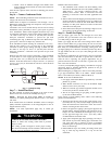

8
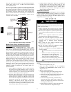
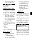
OUT
TEE
NIPPLE
CAP
IN
C99020
Fig. 7 -- Sediment Trap
5. Install an accessible, external, manual main shutoff valve in
gas supply pipe within 6 ft (1.8 m) of heating section.
6. Install ground-- joint union close to heating section between
unit manual shutoff and external manual main shut -- off
valve.
7. Pressure test all gas piping in accordance with local and
national plumbing and gas codes before connecting piping
to unit.
NOTE: Pressure test the gas supply system after the gas supply
piping is connected to the gas valve. The supply piping must be
disconnected from the gas valve during the testing of the piping
systems when test pressure is in excess of 0.5 psig. Pressure test the
gas supply piping system at pressures equal to or less than 0.5 psig.
The unit heating section must be isolated from the gas piping
system by closing the external main manual shutoff valve and
slightly opening the ground-- joint union.
FIRE OR EXPLOSION HAZARD
Failure to follow this warning could result in personal injury,
death and/or property damage.
--Connect gas pipe to unit using a backup wrench to avoid
damaging gas controls.
--Never purge a gas line into a combustion chamber. Never
test for gas leaks with an open flame. Use a commercially
available soap s olution made specifically for the detection of
leaks t o check all connections.
--Use proper length of pipe to avoid stress on gas control
manifold.
--If a flexible connector is required or allowed by authority
having jurisdiction, black iron pipe shall be installed at
furnace gas valve and extend a minimum of 2 in. (51 mm)
outside furnace casing.
--If codes allow a flexible connector, always use a new
connector. do not use a connector which has previously
serviced another gas appliance.
!
WARNING
8. Check for gas leaks at the field--installed and
factory-- installed gas lines after all piping connections have
been completed. Use a commercially available s oap s olution
made specifically for the detection of leaks (or method
specified by local codes and/or regulations).
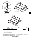
Step 9 — Install Duct Connections
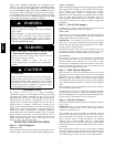
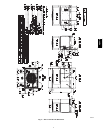
The unit has duct flanges on the supply-- and return-- air openings
on the side and bottom of the unit. For downshot applications, the
ductwork connects to the roof curb (See Fig. 2 and 3 for
connection sizes and locations).
Configuring Units for D ownflow (Vertical) Discharge
ELECTRICAL SHOCK HAZARD
Failure to follow this warning could result in personal injury
or death.
Before installing or servicing system, a lways turn off main
power to system. There may be more than one disconnect
switch. Tag the disconnect switch with a suitable warning
label.
!
WARNING
1. Open all electrical disconnects before starting any service
work.
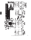
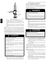
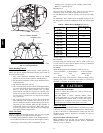
2. Remove horizontal (metal) duct covers to access vertical
(downflow) discharge duct knockouts in unit basepan. (See
Fig. 8.)
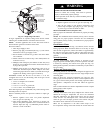
3. Starting in a corner as shown in Fig. 9, score the panel in
both directions from the corner. Tap the panel out from the
scored corner using a small hammer. Be careful and not
damage any other part of the unit.
4. If unit ductwork is to be attached to vertical opening flanges
on the unit base (jackstand applications only), do so at this
time.
PROPERTY DAMAGE HAZARD
Failure to follow this caution may result in property damage.
Collect ALL screws that were removed. Do not leave s crews
on rooftop as permanent damage to the roof may occur.
CAUTION
!
5. It is recommended that the base insulation around the
perimeter of the vertical return-- air opening be secured to
the base with aluminum tape. Applicable local codes may
require aluminum tape to prevent exposed fiberglass.
6. Reinstall both horizontal duct covers. Ensure opening is
air-- and watertight.
7. After completing unit conversion, perform all safety checks
and power up unit.
NOTE: The design and installation of the duct system must be in
accordance with the standards of the NFPA for installation of
nonresidence--type air conditioning and ventilating systems, NFP A
90A or residence-- type, NFPA 90B; and/or local codes and
ordinances.
Adhere to the following criteria when selecting, sizing, and
installing the duct system:
1. Units are shipped for horizontal duct installation (by
removing duct covers).
2. Select and size ductwork, supply-- air registers, and
return--air grilles according to American Society of Heating,
Refrigeration and Air Conditioning Engineers (ASHRAE)
recommendations.
3. Use flexible transition between rigid ductwork and unit to
prevent transmission of vibration. The transition may be
screwed or bolted to duct flanges. Use suitable gaskets to
ensure weather tight and airtight seal.
48VT--A