


10
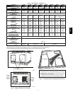
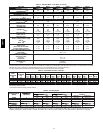
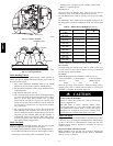
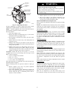
Table 1 -- Physical Data -- Unit 48VT --A Cont’d)
UNITSIZE 048090 048115 048130 060090 060115 060130
NOMINAL CAP ACITY ---ton 4 4 4 5 5 5
SHIPPING WEIGHT---lb
(kg)
513
233
513
233
513
233
543
246
543
246
546
246
COMPRESSORS Scroll
Quantity 1
REFRIGERANT (R---410A)
Quantity ---lb
(kg )
17.0
7.7
17.0
7.7
17.0
7.7
16.0
7.3
16.0
7.3
16.0
7.3
REFRIGERANT METERING DEVICE TXV
OUTDOOR ORIFICE---in. (qty)
(mm)
0.040 (2)
1.02
0.049 (2)
1.24
OUTDOOR COIL
Rows...Fins---in.
Face Area --- sq ft
2...21
19.4
2...21
19.4
2...21
19.4
2...21
23.3
2...21
23.3
2...21
23.3
OUTDOOR FAN
Nominal Cfm
Diameter---in.
(mm)
Motor Hp --- Rpm
3500
22
559
1/4 (1100)
3500
22
559
1/4 (1100)
3500
22
559
1/4 (1100)
3800
22
559
1/3 (1100)
3800
22
559
1/3 (1100)
3800
22
559
1/3 (1100)
INDOOR COIL
Rows...Fins---in.
Face Area --- sq ft
3...17
5.7
3...17
5.7
3...17
5.7
4...17
5.7
4...17
5.7
4...17
5.7
INDOOR BLOWER
Nominal Cooling Airflow---(CFM)
Size --- in.
(mm)
Motor --- hp
1600
11x10
279x254
1.0
1600
11x10
279x254
1.0
1600
11x10
279x254
1.0
1750
11x10
279x254
1.0
1750
11x10
279x254
1.0
1750
11x10
279x254
1.0
FURNACE SECTION*
Burner Orifice
Natural Gas Qty ...Drill Size
Propane GasQty...Drill Size
3...38
3...53
3...33
3...51
3...31
3...49
3...38
3...53
3...33
3...51
3...31
3...49
HIGH---PRESSURE SWITCH (psig)
Cut --- out
Reset (Auto)
650 +/---15
420 +/---25
LOSS --- OF --- CHARGE /
LOW---PRESSURE SWITCH
(Liquid Line) (psig)
Cut --- out
Reset (auto)
20 +/ ---5
45 +/---10
RETURN ---AIR FILTERS †
Throwaway (in.)
(mm)
24x36x1
(610x914x25)
*Based on altitude of 0to 2000 ft (0---610 m).
{Required filter sizes shown are based on the larger of the ARI (Air Conditioning and Refrigeration Institute) rated cooling airflow or the heating airflow velocity of
300 ft/minute for high---capacity type. Air filter pressure drop for non---standard filters must not exceed 0.08 IN. W.C.
} If using accessory filter rack refer to filterrack installation instructions forcorrectfiltersizeand quantity.
Table 2 – Maximum Gas Flow Capacity*
NOMINAL
IRON
PIPE, SIZE
(IN.)
INTERNAL
DIAMETER
(IN.)
LENGTH OF PIPE, FT (m)†
10
(3.0)
20
(6.1)
30
(9.1)
40
(12.2)
50
(15.2)
60
(18.3)
70
(21.3)
80
(24.4)
90
(27.4)
100
(30.5)
125
(31.1)
150
(45.7)
175
(53.3)
200
(61.0)
1/2 .622 175 120 97 82 73 66 61 57 53 50 44 40 — —
3/4 .824 360 250 200 170 151 138 125 118 110 103 93 84 77 72
1 1.049 680 465 375 320 285 260 240 220 205 195 175 160 145 135
1 ---1/4 1.380 1400 950 770 600 580 530 490 460 430 400 360 325 300 280
1 ---1/2 1.610 2100 1460 1180 990 900 810 750 690 650 620 550 500 460 430
* Capacity of pipe in cu ft of gas per hr for gas pressure of 0.5psig or less. Pressure drop of 0.5--IN. W.C. (based on a 0.60 specific gravity gas). Refer to Table 2
and the NFGC NFPA 54/ANSI.
† This lengthincludes an ordinary number of fittings.
Table 3 – Heating Inputs
HEATING INPUT
(BTUH)
NUMBER
OF
GAS SUPPLY PRESSURE (IN. W.C.)
MANIFOLD PRESSURE
NUMBER
OF
ORIFICES
Natural{ Propane*{
MANIFOLD
PRES
SURE
(IN. W.C.)
ORIFICES
Min Max Min Max Natural{ Propane*†
40,000 2 4.0 13.0 11.0 13.0 3.2∼3.8 10.0∼11.0
60,000 2 4.0 13.0 11.0 13.0 3.2∼3.8 10.0∼11.0
90,000 3 4.0 13.0 11.0 13.0 3.2∼3.8 10.0∼11.0
115,000 3 4.0 13.0 11.0 13.0 3.2∼3.8 10.0∼11.0
130,000 3 4.0 13.0 11.0 13.0 3.2∼3.8 10.0∼11.0
*When a unit is converted to propane, different size orifices must be used. See separate, natural---to---propane conversion kit instructions.
{Basedon altitudesf rom sea level to 2000 ft(610 m) above sea level. In th e U.S.A . for altitudes above 2000 ft (610 m), reduce input rating 4percent for each
additional 1000 ft (305 m)above sea level. In Cana da, from 2000 ft (610 m) above sea level to 4500 ft (1372 m) above sea level, derate the unit 10 percent.
48VT--A