


36
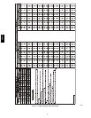
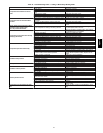
Table 12 – Troubleshooting Guide–Heating
SYMPTOM CAUSE REMEDY
Burners will not ignite
Water in gas li ne Drain. Install drip leg.
No power to furnace Check power supply fuses, wiring or circuit breaker.
No 24--v power supply to control circuit
Check transformer.
NOTE: Some transformers have i nternal over--current protection
that requires a cool--down period to reset.
Mis--wired or loose connections Check all wiring and wire nut connections
Misaligned spark electrodes
Check flame igniti onand sense electrode positioning.
Adjust as necessary.
No gas at main burners
1. Check gas line f or air. Purge as necessary. NOTE: After purging
gas line of air, wait a tleast 5 minutes for any gas to dissipate be-
fore attempting tolight unit.
2. Check gas valve.
Inadequate heating
Dirty air filter Clean or replace fi lter as necessary
Gas input to furnace too low Check gas pressure at manifold match with t haton unit nameplate
Unit undersized for application Replace with proper unit or add additionalunit
Restricted airflow Clean or replace fi lter. R emove any restriction.
Limit switch cyclesmain burners
Check rotation of blower, temperature rise of unit. Adjust as neces-
sary.
Poor flame characteristics
Incomplete combustion results in: Aldehyde odors,
carbon monoxide, sootingflame, f loating flame
1. Tighten all screws around burner compartment
2. Cracked heat exchanger. Replace.
3. Unit over--fired. Reduce input (change orifi ces or adjust gas line
or manifold pressure).
4. Check burner alignment.
5. Inspect heat exchanger for blockage. Clean as necessary.
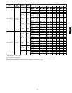
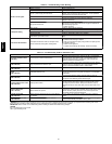
Table 13 – Troubleshooting Guide–LED Status Codes
SYMPTOM CAUSE REMEDY
No Power Hardware failure
(LEDOFF)
Loss of power to control module(IGC)*.
Check 5--amp fuse son IGC*, power to unit,24--v circuit breaker,
and transformer. Units without a 24--v circuit breaker have an
internal overload i nthe 24--v transformer. If the overload trips,
allow 10 minutes for automatic reset.
Limit switch faults
(LED 2 flashes)
High temperature limit switch is open.
Check the operation of the indoor (evaporator) fan motor. Ensure
that the supply--air temperature rise is in accordance with the
range on the unit nameplate. C lean or replace filters.
Flame sense fault
(LED 3 flashes)
The IGC* sensed flame that should notbe present. Reset uni t.If problem persists, replace control board.
4 consecutive limit switch
faults
(LED 4 flashes)
Inadequate ai rflow tounit.
Check the operation of the indoor (evaporator) fan motor and that
supply--air temperature rise agrees with range onunit nameplate
information.
Ignition lockout
(LED 5 flashes)
Unit unsuccessfully attempted ignition for 15 minutes.
Check ignitor and fl amesensor electrode spacing, gaps, etc.
Ensure that fame sense and ignition wires are properly terminated.
Verify that unitis obtaining proper amount of gas.
Pressure S witch motor fault
(LED 6 flashes)
Open pressureswitch.
Verify wiring connections to pressure switch and i nducer motor.
Verify pressure switch hose is tightly connected to bothinducer
housing and pressure switch. Verify inducer wheel i s properly
attached to i nducer motor shaft. Verify inducer motor shaft is turn-
ing.
Rollout switch fault
(LED 7 flashes)
Rollout switch has opened.
Rollout switch will automatically reset, but IGC* wi ll continue to
lockout unit. Check gas valve operation. Ensure that induced--draft
blower wheel is properly secured to motor shaft. Inspect heat
exchanger. Reset unit at unit disconnect.
Internal control fault
(LED 8 flashes)
Microprocessor has sensed an error inthe software
or hardware.
If error code is not cleared by resetting unitpower, replace the
IGC*.
Temporary 1 hrauto reset
(LED 9 flashes)
Electrical interference impeding IGC software
Reset 24--v. to control board or turn thermostat off, then on again.
Fault willautomatically reset i tself in one (1) hour.
*WARNING : If the IGCmust be replaced, be sure toground yourselfto dissipate any electrical charge that my be present before handlingnew control
board.Th e IGC is sensitive to static electricity andmy be damaged if the necessary precautions are not taken.
IMPORTANT: Refer to Table 12---Troubleshooting Guide---Heating for additional troubleshooting analysis.
LEGEND
IGC—Integrated Gas Unit Controller
LED—Light---EmittingDiode
48VT--A