


This configuration provides the following comfort enhance-
ments:
(a.) A 30 sec blower on delay with 150 sec at 70 percent
airflow to allow the indoor coil to warm up or cool
down before the blower is asked to deliver 100 percent
airflow reducing the cold blow sensation at start up in
heating and allowing the indoor coil to more quickly
reach wet coil operating conditions in cooling.
(b.) A no blower off delay eliminates cold blow which may
be associated with running the blower after shut down
of the compressor and avoids re-evaporation of con-
densed moisture after cooling/dehumidifying opera-
tion.
(c.) Lower airflow while the compressor is running to
reduce draft effects and increase heating air tempera-
ture and improved humidity control during cooling
operation.
ACCESSORY INSTALLATION
a. ACCESSORY ELECTRIC HEATERS
Electric heaters may be installed with the 50GL & 50JZ units
per instructions supplied with electric heater package. See unit
rating plate for factory-approved electric heater kits.
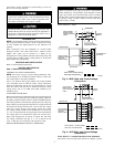
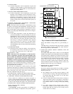
b. AUXILIARY TERMINALS
The AUX and HUM terminals on the Easy Select™ Board are
tied directly to the G terminal, and provide a 24-v. signal
whenever the G terminal is energized (See Fig. 12). During
Super dehumidify mode, the G signal is not present and the
auxiliary terminals are not energized. If the installation includes
the use of the operating mode, do not use these terminals to
control accessories. See Electronic Air Cleaner and Humidifier
sections for further information.
c. ELECTRONIC AIR CLEANER CONNECTIONS
The AUX1 and AUX2 terminals are not always energized
during blower operations, as described above. When using an
electronic air cleaner with the unit, use Airflow Sensor P/N
KEAAC0101AAA. The airflow sensor turns on electronic air
cleaner when the blower is operating.
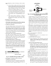
d. HUMIDIFIER/HUMIDISTAT CONNECTIONS
Easy Select™ Board terminals HUM1 and HUM2 are provided
for direct connection to the low-voltage control of a humidifier
through a standard humidistat (See Fig. 12). These terminals are
energized with 24-v. when G thermostat signal is present. (See
Fig. 11, 12 & 13). Alternately, the 24-v. signal may be sourced
from the W and C circuit board connections. When using a
Thermidistat™ Control, Zone Comfort Plus or Comfort Zone
II, the 24-v. signal may be sourced directly from the Thermi-
distat™ HUM terminal.
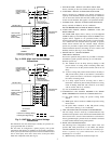
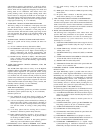
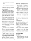
e. DEHUMIDIFY CAPABILITY WITH STANDARD
HUMIDISTAT CONNECTION
Latent capacities for these units are better than average systems.
If increased latent capacity is an application requirement, the
circuit board provides connection terminals for use of a
standard humidistat. The unit will detect the humidistat contacts
opening on increasing humidity and reduce its airflow to
approximately 80 percent of nominal cooling mode airflow.
This reduction will increase the system latent capacity until the
humidity falls to a level which causes the humidistat to close its
contacts. When the contacts close, the airflow will return to 100
percent of selected cooling airflow. To activate this mode,
remove jumper J1 and wire in a standard humidistat ( See Fig.
13).
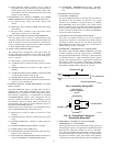
f. DEHUMIDIFY AND SUPER DEHUMIDIFY CAPABILITIES
these models are capable of responding to a signal from indoor
system control (thermostat, Thermidistat™, zoning control) to
operate in comfort control modes such as Super Dehumidify
Mode. Consult literature provided with indoor system control to
determine if these operating modes are available, and to see
control set up instructions. No special setup or wiring of unit is
required.
50GL & 50JZ SEQUENCE OF OPERATION
a. CONTINUOUS FAN
(1.) Thermostat closes circuit R to G—The Blower runs at
continuous fan airflow.
b. COOLING MODE-LOW HUMIDITY
(1.) If indoor temperature is above temperature set point and
humidity is below humidity set point, thermostat closes
circuits R to G, R to Y/Y2 and R to O—The unit delivers
cooling airflow.
c. COOLING MODE-DEHUMIDIFICATION
(1.) If indoor temperature is above temperature set point and
humidity is above humidity set point, thermostat or Ther-
midistat™ closes circuits R to G, R to O, and R to Y/Y2
and humidistat or Thermidistat™ opens R to DH—The
unit delivers airflow which is approximately 80 percent of
the nominal cooling airflow to increase the latent capacity
of the system.
d. COOLING MODE-SUPER DEHUMIDIFY OPERATION (see
quick reference guide)
NOTE: The indoor control used, such as a Thermidistat™, must
be capable of providing Super Dehumidify operation mode and
control must be configured as outlined in its installation instruc-
tions. Consult indoor control literature to determine if control is
capable of providing Super Dehumidify inputs and for configura-
tion instruction.
(1.) If the indoor temperature is below the temperature set
point and the humidity is above the humidity set point, the
Thermidistat™ closes circuit R to O, opens circuits R to
DH and R to G, and cycles circuit R to Y/Y2. If circuit R
to G is closed (24-v.), the motor will deliver airflow at the
full cooling or cooling plus dehumidify mode requested
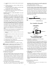
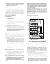
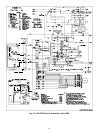
Fig. 12—Humidifier Wiring for 50GL & 50JZ
A95317
HUMIDISTAT
TO HUMIDIFIER
HUMIDIFIER WIRING
HUM 1
(C)
HUM 2
(G)
24-VAC
Fig. 13—Humidistat Wiring for De-Humidify Mode-
for 50GL & 50JZ
A95316
EASY SELECT
BOARD TERMINAL
BLOCK
D
H
J1
R
HUMIDISTAT
REMOVE
JUMPER
9