


value. If circuit R to G is open (0–v.) for super dehumidify
mode, the motor delivers reduced airflow to maximize the
humidity removal of the system while minimizing over
cooling.
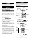
e. ELECTRIC HEATING MODE
(1.) Thermostat closes circuit R to W/W1, or W2—The unit
delivers the selected electric heat airflow. There are no on
or off delays.
f. HEAT PUMP HEATING MODE (50JZ only)
(1.) Thermostat closes circuits R to G and R to Y/Y2—The unit
delivers selected heat pump heating airflow.
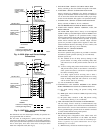
g. HEAT PUMP HEATING WITH AUXILIARY
ELECTRIC HEAT (50JZ only)
(1.) Thermostat closes circuits R to G, R to Y/Y2 and R to
W/W1 or W2 (and R to O in the case of defrost).
In the event that electric heating is called for by the thermostat
while the heat pump is also operating in either heating or
defrost modes, the motor will modify its airflow output, if
necessary, to provide an airflow which is defined as safe for the
operation of the electric heater during heat pump operation.
That airflow is the greater of the heat pump heating airflow and
the electric heater only airflow.
h. HEATING MODE—SUPER COMFORT HEAT OPERA-
TION
NOTE: The indoor control used, such as a Thermidistat™, must
be capable of providing Super Comfort Heat operation mode and
control must be configured as outlined in its installation instruc-
tions. The system must be installed with appropriate outdoor
temperature sensor. Consult indoor control literature to determine
if control is capable and for configuration instructions. Consult
indoor control instructions and sensor instructions for sensor
installation details.
If the outdoor temperature is in the range of 12° to 40° F, the
Thermidistat™ closes circuit R to Y/Y2 and opens circuit R to G.
If circuit R to G is closed (24-v.), the motor will deliver airflow at
the full heating requested value. If circuit R to G is open (0-v.) for
maximum heating comfort, the motor delivers reduced airflow to
maximize the temperature and minimize the draft effect of the
heated air leaving the unit.
ICM FIOP START-UP
ICM General Start Up
CHECKING AND ADJUSTING REFRIGERANT CHARGE
The refrigerant system is fully charged with Puron® (R-410A)
refrigerant, and is tested and factory sealed.
NOTE: Adjustment of the refrigerant charge is not required
UNLESS the unit is suspected of not having the proper R-410A
charge.
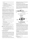
The charging label and the tables shown refer to system tempera-
tures and pressures. The temperatures and pressures are calculated
at rated airflow. When charging unit, set to rated airflow. A
refrigerant charging chart label is attached to the outside of the
compressor access door. The chart includes the required suction
line temperature at given suction line pressures and outdoor
ambients. An accurate superheat, thermocouple- or thermistor-type
thermometer, and gage manifold are required when using the
superheat charging method for evaluating the unit charge. Do not
use mercury or small dial-type thermometers because they are
not adequate for this type of measurement
IMPORTANT: When evaluating the refrigerant charge, an indi-
cated adjustment to the specified factory charge must always be
very minimal. If a substantial adjustment is indicated, an abnormal
condition exists somewhere in the cooling system, such as insuf-
ficient airflow across either one or both coils.
Step 1—48GP Start-Up (ICM FIOP)
CHECKING COOLING CONTROL OPERATION-Start and
check the unit for proper cooling control operation as follows:
(1.) Place room thermostat SYSTEM switch in OFF position.
Observe that blower motor starts when FAN switch is
placed in ON position and shuts down when FAN switch
is placed in AUTO position. Note fan delay time setting
selected on the Easy Select™ board. (See Easy Select
Section.)
(2.) Place SYSTEM switch in COOL position and FAN switch
in AUTO position. Set cooling control below room tem-
perature. Observe that compressor, condenser fan, and
evaporator blower motors start. Observe that cooling cycle
shuts down when control setting is satisfied. The evapo-
rator fan will continue to run for the time setting selected
on Easy Select™ board. (See Easy Select Section.)
(3.) When using an auto-changeover room thermostat, place
both SYSTEM and FAN switches in AUTO position.
Observe that unit operates in heating mode when tempera-
ture control is set to “call for heating” (above room
temperature) and operates in cooling mode when tempera-
ture control is set to “call for cooling” (below room
temperature).
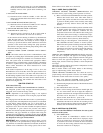
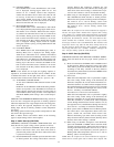
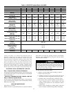
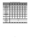
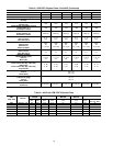
AIRFLOW AND TEMPERATURE RISE-The heating section for
each size unit is designed and approved for heating operation
within the temperature rise range stamped on the unit rating plate.
Table 15 shows the approved temperature rise range for each
heating input, and the air delivery (CFM) at various temperature
rise ranges.
The heating operation airflow must produce a temperature rise that
falls with in the approved range.
Refer to Indoor Airflow and Airflow Tables on the following
pages to adjust heating airflow when required.
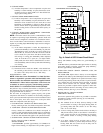
CHECK HEATING CONTROL-Start and check the unit for
proper heating control operation as follows. (see furnace lighting
instructions located inside burner or blower access panel.):
(1.) Place room thermostat SYSTEM switch in the HEAT
position and the FAN switch in the AUTO position.
(2.) Set the heating temperature control of the thermostat above
room temperature.
(3.) The induced-draft motor will start.
(4.) After a call for heating, the main burner should light with
in 5 sec. If the burners still do not light, this sequence is
repeated. If the burners do not light within 15 minutes from
the initial call for heat, there is a lockout. To reset the
lockout control, break the 24-v. power to W.
(5.) The indoor fan will turn on 45 sec after the flame has been
established. The indoor fan will turn off according to time
delay selected on the Easy Select™ board (See Easy Select
Section) after the thermostat has been satisfied.
Step 2—48JZ Start-Up (ICM FIOP)
Also refer to the Thermidistat™ instructions for start up and
check out of the system.
(1.) FAN OPERATION—
The fan button on Thermidistat™ switches fan icon
between AUTO and ON. While ON is displayed, output
will be on, turning fan on. Allow up to 10 sec. after button
is pressed for fan to turn on and off. the fan will continue
to run for the time setting selected on the Easy Select™
board after AUTO icon is displayed.
10