


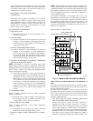
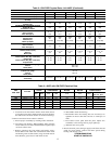
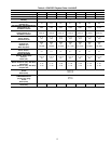
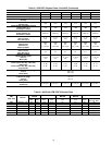

The ICM motor uses the selected taps to modify its operation to a
pre-programmed table of airflows.
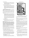
The unit must be configured to operate properly with system
components with which it is installed. To successfully configure a
basic system (see information printed on circuit board label located
next to select pins), move the 6 select wires to the pins which
match the components used (See Fig. 8).
a. GAS HEAT/CFM—SELECT GAS HEAT INPUT SIZE
Factory selected gas heat size should correspond to unit label.
b. AC/HP SIZE—SELECT SYSTEM SIZE INSTALLED
Factory selected air conditioner size should correspond to
capacity of unit installed. Installer should verify air conditioner
size to ensure that airflow delivered falls within proper range
for the size unit installed. This applies to all operational modes.
c. SYSTEM TYPE—SELECT SYSTEM TYPE INSTALLED
Factory selected on 48GP for AC-Air conditioner.
For Gas Heat/Electric Cool Unit–AC must be selected.
d. AC/HP CFM ADJUST—SELECT NOMINAL, LOW, OR
HIGH AIRFLOW
The AC/HP CFM Adjust select is factory set to the High-HI
(NOM for 060) tap. The CFM Adjust selections NOM/LO will
regulate airflow supplied for all operational modes, except
non-heat pump heating modes. HI provides 15 percent airflow
over nominal unit size selected and LO provides 10 percent
airflow below nominal unit size selected. Adjust selection
options are provided to adjust airflow supplied to meet indi-
vidual installation needs for such things as noise, comfort, and
humidity removal (See Fig. 8, D as indicated).
e. ON/OFF DELAY—SELECT DESIRED
TIME DELAY PROFILE
Four motor operation delay profiles are provided to customize
and enhance system operation (See Fig. 8, E as indicated).
Selection options are:
(1.) The standard 90 sec off delay (Factory Setting) at 100
percent airflow in cooling mode. In heating mode, IGC
will control 45 sec on delay with no airflow and 45 sec off
delay.
(2.) A 30 sec cooling delay with no airflow/ 90 sec off delay at
100 percent airflow profile is used when it is desirable to
allow system coils time to cool-down in conjunction with
the airflow in heating mode.
(3.) A no delay option used for servicing unit or when a
thermostat is utilized to perform delay functions in cooling
mode. In heating mode IGC will control 45 sec on delay
with no airflow and 45 sec off delay.
(4.) Not recommended for 48GP
f. CONTINUOUS FAN—SELECT DESIRED FAN SPEED
WHEN THERMOSTAT IS SET ON CONTINUOUS FAN
(1.) LO speed—Factory setting, 50 percent cooling mode
airflow.
(2.) MED speed—Move connector to MED, 65 percent cooling
mode airflow.
(3.) HI speed—Move connector to HI, 100 percent cooling
mode airflow (See Fig. 8, F as indicated).
g. LOW-VOLTAGE CIRCUIT FUSING AND REFERENCE
The low-voltage circuit is fused by a board-mounted 5–amp
automotive fuse placed in series with the transformer SEC2 and
the R circuit. The C circuit of the transformer is referenced to
chassis ground through a printed circuit run at SEC1 connected
to metal standoff marked with ground symbol.
h. BASIC UNIT CONFIGURATION
The following basic configuration of the indoor motor will
provide ARI rated performance of the 48GP. This BASIC
CONFIGURATION should be used when the rated ARI perfor-
mance is required, or if system enhancements such as super
dehumidify are not needed.
(1.) HEAT-Factory selected to match heat input size.
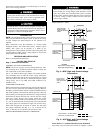
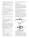
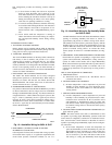
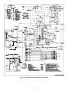
Fig. 4—50GL High- and Control-Voltage
Connections
C01027
POWER
SUPPLY
FIELD-SUPPLIED
FUSED DISCONNECT
HIGH VOLTAGE
POWER LEADS
(SEE UNIT WIRING
LABEL)
GND
CONTROL BOX
SPLICE BOX
LOW-VOLTAGE
POWER LEADS
(SEE UNIT
WIRING LABEL)
YEL(Y)
GRN(G)
RED(R)
BRN(C)
THERMOSTAT
(TYPICAL)
LEGEND
Field Control-Voltage Wiring
Field High-Voltage Wiring
BLK(DH)
DHUM
Y
G
R
C
W1
WHI(W1)
GRA(W2)
W2
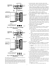
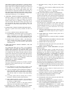
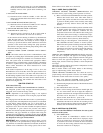
Fig. 5—50JZ High- and Control-Voltage
Connections
C01028
POWER
SUPPLY
FIELD-SUPPLIED
FUSED DISCONNECT
HIGH VOLTAGE
POWER LEADS
(SEE UNIT WIRING
LABEL)
GND
CONTROL BOX
SPLICE BOX
LOW-VOLTAGE
POWER LEADS
(SEE UNIT
WIRING LABEL)
YEL(Y)
GRN(G)
RED(R)
BRN(C)
THERMOSTAT
(TYPICAL)
LEGEND
Field Control-Voltage Wiring
Field High-Voltage Wiring
BLK(DH)
DHUM
Y
G
R
C
W1
WHI(W1)
GRA(W2)
W2
ORN(0)
O
3