


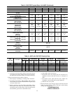

(2.) AC/HP Size-Factory selected to match system size, please
verify.
(3.) SYSTEM TYPE-Factory selected on 48GP system AC-
AIR CONDITIONER.
(4.) AC/HP CFM ADJUST-Select HIGH for 042 & 048, NOM
for 036 & 060, and LO for 024 & 030..
(5.) ON/OFF DELAY-Factory selected 0/90 profile.
(6.) CONTINUOUS FAN-Select desired fan speed when ther-
mostat is set to continuous fan.
i. COMFORT OPTIONS—SUPER DEHUMIDIFY (See Quick
Reference Guide)
The Super Dehumidify option is possible when this unit is
installed with a field supplied Thermidistat™ control (Super-
Dehumidify does not require an outdoor temperature sensor).
The following configuration is recommended for maximum
cooling/dehumidifying comfort. This configuration will im-
prove the comfort provided by the air conditioning system if
more humidity removal is desired. While providing this im-
proved comfort, the system will operate efficiently, but not at
the published ARI SEER efficiency. During cool-to-dehumidify
call, it provides maximum dehumidification by reducing airflow
to a minimum. The actual super dehumidify command from
Thermidistat™ control to the indoor unit is a “Y” signal without
a “G” signal in addition to dehumidify signal. The indoor unit
responds to this combination by reducing the airflow to a
minimum. All other characteristics of cool to dehumidify are the
same.
The following system configuration is recommended for maxi-
mum cooling/dehumidifying comfort (See Fig. 8).
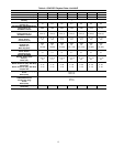
(1.) HEAT-Factory selected to match gas heat size of unit
installed.
(2.) AC/HP Size-Factory selected to match system size, please
verify.
(3.) SYSTEM TYPE-Factory selected on 48GP system AC-
AIR CONDITIONER.
(4.) AC/HP CFM ADJUST-Select NOM (Lo for 060).
(5.) ON/OFF DELAY-Select ENH profile.
(6.) CONTINUOUS FAN-Select desired fan speed when ther-
mostat is set to continuous fan.
(7.) DEHUMIDIFY MODE-Remove J1 jumper to activate.
NOTE: J1 jumper should only be removed when a Thermidis-
tat™, humidistat or capable zoning control is installed.
(8.) LOW VOLTAGE CONNECTIONS-Make connections as
shown in ELECTRICAL CONNECTIONS section.
(9.) CONFIGURE THERMIDISTAT™-Follow Thermidis-
tat™ (or capable zoning system) installation instructions
for Super Dehumidify operation.
ACCESSORY INSTALLATION
a. AUXILIARY TERMINALS
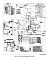
The AUX and HUM terminals on the Easy Select™ Board are
tied directly to the G terminal, and provide a 24-v. signal
whenever the G terminal is energized (See Fig. 6). During
Super dehumidify mode, the G signal is not present and the
auxiliary terminals are not energized. If the installation includes
the use of this operating mode, do not use these terminals to
control accessories. See Electronic Air Cleaner and Humidifier
sections for further information.
b. ELECTRONIC AIR CLEANER CONNECTIONS
The AUX1 and AUX2 terminals are not always energized
during blower operations, as described above. When using an
electronic air cleaner with the unit, use Airflow Sensor P/N.
KEAAC0101AAA. The airflow sensor turns on electronic air
cleaner when the blower is operating.
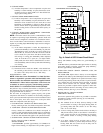
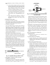
c. HUMIDIFIER/HUMIDISTAT CONNECTIONS
Easy Select™ Board terminals HUM1 and HUM2 are provided
for direct connection to the low-voltage control of a humidifier
through a standard humidistat (See Fig. 6). These terminals are
energized with 24-v. when G thermostat signal is present (See
Fig. 6 & 7). Alternately, the 24-v. signal may be sourced from
the W and C on the 9 pin connector. When using a Thermidis-
tat™ Control, Zone Comfort Plus or Comfort Zone II, the 24-v.
signal may be sourced directly from the Thermidistat™ HUM
terminal (See Fig. 6,7&8).
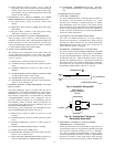
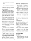
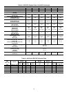
d. DEHUMIDIFY CAPABILITY WITH STANDARD
HUMIDISTAT CONNECTION
Latent capacities for this unit are better than average systems. If
increased latent capacity is an application requirement, the ICM
board provides connection terminals for use of a standard
humidistat. The unit will detect the humidistat contacts opening
on increasing humidity and reduce its airflow to approximately
80 percent of nominal cooling mode airflow. This reduction
will increase the system latent capacity until the humidity falls
to a level which causes the humidistat to close its contacts.
When the contacts close, the airflow will return to 100 percent
of selected cooling airflow. To activate this mode, remove
jumper J1 and wire in a standard humidistat (See Fig. 7).
e. DEHUMIDIFY AND SUPER DEHUMIDIFY
CAPABILITIES
This model unit is capable of responding to a signal from indoor
system control (Thermidistat™ or capable zoning control) to
operate in comfort control modes such as Super Dehumidify
Mode. Consult literature provided with indoor system control to
determine if these operating modes are available, and to see
control set up instructions. No special setup or wiring of unit is
required.
48GP SEQUENCE OF OPERATION
a. CONTINUOUS FAN
(1.) Thermostat closes circuit R to G—The Blower runs at
continuous fan airflow
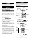
Fig. 6—Humidifier Wiring-48GP
A95317
HUMIDISTAT
TO HUMIDIFIER
HUMIDIFIER WIRING
HUM 1
(C)
HUM 2
(G)
24-VAC
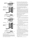
Fig. 7—Humidistat Wiring for
De-Humidify Mode-48GP
A95316
EASY SELECT
BOARD TERMINAL
BLOCK
D
H
J1
R
HUMIDISTAT
REMOVE
JUMPER
4