


(2.) COOLING MODE—
Press MODE button on the Thermidistat™ until COOL
icon is displayed. Cooling begins within 10 sec. and
remains on for 4 minutes. Observe that compressor,
outdoor fan and indoor blower motors start after the call
for Cooling. At the end of 4 minutes, the cooling cycle
stops and the MODE reverts back to OFF. The Indoor
Blower continues to run for the time selected on the Easy
Select™ board after OFF icon is displayed.
(3.) HEAT PUMP HEATING—
Press MODE button on the Thermidistat™ until HEAT
icon is displayed. Heat pump heating begins within 10 sec.
and remains on for 4 minutes. Observe that the compres-
sor, outdoor fan and indoor blower come on. At the end of
the 4 minutes, heating cycle stops and the MODE reverts
back to OFF. The indoor blower continues to run for the
time selected on the Easy Select™ Board after the OFF
icon is displayed. Heating maybe turned off anytime
during the 4 minute cycle by pressing MODE button until
OFF is displayed.
(4.) GAS HEAT MODE—
Press MODE button until E-HEAT(Emergency Heat or
Back-Up Heat) icon is displayed. Gas heating begins
within 10 sec. and remains on for 4 minutes. The induced
draft motor should start immediately. The burners should
light within 5 sec. of E-HEAT call. The indoor blower will
turn on 45 sec. after the flame has been established. Gas
heating stops at the end of 4 minutes and MODE reverts
back to OFF. The indoor blower continues to run for the
time selected on the Easy Select™ Board after the OFF
icon is displayed.
NOTE: If the burners do not light, this lighting sequence is
repeated for 15 minutes from the initial call for E-HEAT. If after
15 minutes the burners do not light, there will be a lockout. To
reset the burner lockout control, break the 24-v. power to “W”.
(5.) AUTOMATIC CHANGE-OVER—
To test AUTO CHANGE-OVER function between COOL
and HEAT:
Enable the AUTO CHANGE-OVER mode during Thermi-
distat™ set-up. Refer to the Thermidistat™ literature for
details. Observe that the unit operates in cooling when in
COOL MODE (when setting is below room temperature)
and HEAT MODE (when setting is above room tempera-
ture).
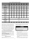
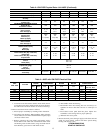
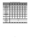
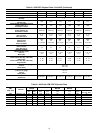
AIRFLOW AND TEMPERATURE RISE-The heating section for
each size unit is designed and approved for heating operation
within the temperature rise range stamped on the unit rating plate.
Table 15 shows the approved temperature rise range for each
heating input, and the air delivery (CFM) at various temperature
rise ranges.
The heating operation airflow must produce a temperature rise that
falls with in the approved range.
Refer to Indoor Airflow and Airflow Tables on the following
pages to adjust heating airflow when required.
Step 3—50GL: Start-Up (ICM FIOP)
CHECKING COOLING CONTROL OPERATION–Start and
check the unit for proper cooling control operation as follows:
(1.) Place room thermostat SYSTEM switch in OFF position.
Observe that blower motor starts when FAN switch is
placed in ON position and shuts down when FAN switch
is placed in AUTO position.
(2.) Place SYSTEM switch in COOL position and FAN switch
in AUTO position. Set cooling control below room tem-
perature. Observe that compressor, condenser fan, and
evaporator blower motors start. Observe that cooling cycle
shuts down when control setting is satisfied. The evapo-
rator fan will continue to run for the selected off delay.
(3.) When using an auto-changeover room thermostat, place
both SYSTEM and FAN switches in AUTO positions.
Observe that unit operates in heating mode when tempera-
ture control is set to ‘‘call for heating’’ (above room
temperature) and operates in cooling mode when tempera-
ture control is set to ‘‘call for cooling’’ (below room
temperature).
NOTE: Once the compressor has started and then has stopped, it
will not start again until 5 minutes have elapsed. (The cooling
cycle remains ‘‘on’’ until the room temperature drops to point that
is slightly below the cooling control setting of the room thermostat.
At this point, the thermostat ‘‘breaks’’ the circuit between ther-
mostat terminal R to terminals Y and G.) These open circuits
de-energize contactor coil C and ICM board. The condenser and
compressor motors stop. After the time delay setting selected on
the Easy Select™ board (See Easy Select Section) , the blower
motor stops. The unit is in a ‘‘standby’’ condition, waiting for the
next ‘‘call for cooling’’ from the room thermostat.
Step 4—50JZ: Start-Up (ICM FIOP)
CHECKING COOLING AND HEATING CONTROL OPERA-
TION– Start and check the unit for proper control operation as
follows:
(1.) Place room thermostat SYSTEM switch or MODE control
in OFF position. Observe that blower motor starts when
FAN mode is placed in FAN ON position and shuts down
according to time delay selected on the Easy Select™
board (See Easy Select Section) when FAN MODE switch
is placed in AUTO position.
(2.) Thermostat:
When the room temperature rises to a point that is slightly
above the cooling control setting of the thermostat, the
thermostat completes the circuit between thermostat ter-
minal R to terminals Y, O and G. These completed circuits
through the thermostat connect contactor coil (C) (through
unit wire Y) and ICM board (through unit wire G) across
the 24-v. secondary of transformer (TRAN).
Thermidistat™ or Thermostat and Humidistat:
When the room temperature rises to a point that is slightly
above the cooling control setting of the thermostat, the
thermostat completes the circuit between thermostat ter-
minal R to terminals Y, O, DH, and G. These completed
circuits through the thermostat connect contactor coil (C)
(through unit wire Y) and ICM board (though unit wire G)
across the 24-v. secondary of transformer (TRANS).
(3.) Place system switch or MODE control in HEAT position.
Set control above room temperature. Observe that com-
pressor, outdoor fan, and indoor blower motors start.
Observe that heating cycle shuts down according to time
delay selected on the Easy Select™ board (See Easy Select
Section) when control setting is satisfied.
(4.) When using an automatic changeover room thermostat,
place both SYSTEM or MODE control and FAN mode
switches in AUTO positions. Observe that unit operates in
Cooling mode when temperature control is set to “call for
Cooling” (below room temperature), and unit operates in
Heating mode when temperature control is set to “call for
Heating” (above room temperature).
NOTE: Once the compressor has started and then has stopped, it
should not be started again until 5 minutes have elapsed. The
11