


18
Step 4 — Start--up Cooling and Make Adjust-
ments
Complete the required procedures given in the Pre--Start--Up
section before starting the unit. Do not jumper any safety devices
when operating the unit. Do not operate the compressor when the
outdoor temperature is below 40°F(4.4°C) (unless accessory
low--ambient kit is installed). Do not rapid--cycle the compressor.
Allow 5 minutes between on cycles to prevent compressor damage.
Checking Cooling Control Operation
Start and check the unit for proper cooling control operation as
follows:
1. Place room thermostat SYSTEM switch in OFF position.
Observe that blower motor starts when FAN switch is
placed in ON position and shuts down when FAN switch is
placed in AUTO position.
2. Place SYSTEM switch in COOL position and FAN switch
in AUTO position. Set cooling control below room
temperature. Observe that compressor, condenser fan, and
evaporator blower motors start. Observe that cooling cycle
shuts down when control setting is satisfied. The evaporator
fan will continue to run for 90 sec.
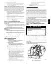
IMPORTANT: Three--phase, scroll compressors units are
direction oriented. Unit must be checked to ensure proper
compressor 3--phase power lead orientation. If not corrected within
5 minutes, the internal protector will shut off the compressor. The
3--phase power leads to the unit must be reversed to correct
rotation. When turning backwards, the difference between
compressor suction and discharge pressures will be near zero.
Checking and Adjusting Refrigerant Charge
The refrigerant system is fully charged with PuronR (R--410A)
refrigerant and is tested and factory sealed. Allow system to operate
a minimum of 15 minutes before checking or adjusting charge.
NOTE: Adjustment of the refrigerant charge is not required unless
the unit is suspected of not having the proper PuronR (R--410A)
charge.
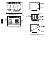
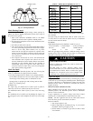
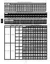
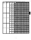
The charging label and the tables shown refer to system
temperatures and pressures in cooling mode only. A refrigerant
charging label is attached to the inside of the compressor access
panel (see Fig. 19). The chart includes the required liquid line
temperature at given discharge line pressures and outdoor ambient
temperatures.
An accurate thermocouple-- or thermistor--type thermometer, and a
gauge manifold are required when using the subcooling charging
method for evaluating the unit charge. Do not use mercury or small
dial--type thermometers because they are not adequate for this type
of measurement.
UNIT DAMAGE HAZARD
Failure to follow this caution may result in unit damage.
When evaluating the refrigerant charge, an indicated
adjustment to the specified factory charge must always be
very minimal. If a substantial adjustment is indicated, an
abnormal condition exists somewhere in the cooling system,
such as insufficient airflow across either coil or both coils.
!
CAUTION
Proceed as follows:
1. Remove caps from low-- and high--pressure service fittings.
2. Using hoses with valve core depressors, attach low-- and
high--pressure gauge hoses to low-- and high--pressure
service fittings, respectively.
3. Start unit in Cooling Mode and let unit run until system
pressures stabilize.
4. Measure and record the following:
a. Outdoor ambient--air temperature (°F[°C] db).
b. Liquid line temperature (°F[°C]).
c. Discharge (high--side) pressure (psig).
d. Suction (low--side) pressure (psig) (for reference only).
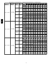
5. Using “Cooling Charging Charts,” compare outdoor--air
temperature(°F[°C] db) with the discharge line pressure
(psig) to determine desired system operating liquid line
temperature (See Fig. 17).
6. Compare actual liquid line temperature with desired liquid
line temperature. Using a tolerance of ± 2°F(±1.1°C), add
refrigerant if actual temperature is more than 2°F(1.1°C)
higher than proper liquid line temperature, or remove
refrigerant if actual temperature is more than 2°F(1.1°C)
lower than required liquid line temperature.
NOTE: If the problem causing the inaccurate readings is a
refrigerant leak, refer to the Check for Refrigerant Leaks section.
Indoor Airflow and Airflow Adjustments
UNIT OPERATION HAZARD
Failure to follow this caution may result in unit damage.
For cooling operation, the recommended airflow is 350 to
450 cfm for each 12,000 Btuh of rated cooling capacity. For
heating operation, the airflow must produce a temperature
rise that falls within the range stamped on the unit rating
plate.
CAUTION
!
NOTE: Be sure that all supply--and return--air grilles are open,
free from obstructions, and adjusted properly.
ELECTRICAL SHOCK AND EXPLOSION HAZARD
Failure to follow this warning could result in personal
injury or death.
Before making any indoor wiring adjustments, shut off gas
supply. Then disconnect electrical power to the unit and
install lockout tag before changing blower speed.
!
WARNING
This unit has independent fan speeds for gas heating and cooling.
In addition, this unit has the field-selectable capability to run two
different cooling fan speeds: A normal cooling fan speed (350~400
CFM/Ton) and an enhanced dehumidification fan speed (As low as
320 CFM/Ton) for use with either a dehumidistat or a thermostat
that supports dehumidification.
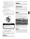
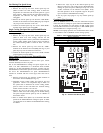
This unit is factory-set up for use with a single cooling fan speed.
The cooling speed is marked “LOW” on the interface fan board
(IFB) (See Fig. 14) . The factory-shipped settings are noted in
Table 10. There are 3 additional speed tap wires available for use
in either gas heating or cooling (For color coding on the indoor fan
motor leads, see Table 6). The additional 3 speed tap wires are
shipped loose with vinyl caps and are located in the control box,
near the interface fan board (IFB) (See Fig. 14).
48EZ --A