


15
4. Verify the following conditions:
a. Make sure gas line is free of air. Before lighting the unit
for the first time, perform the following with the gas
valve in the “OFF” position:
NOTE: If the gas supply pipe was not purged before connecting
the unit, it will be full of air. It is recommended that the ground
joint union be loosened, and the supply line be allowed to purge
until the odor of gas is detected. Never purge gas lines into a
combustion chamber. Immediately upon detection of gas odor,
retighten the union. Allow 5 minutes to elapse, then light unit.
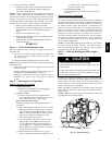
b. Make sure that condenser--fan blade is correctly
positioned in fan orifice. Leading edge of condenser--fan
blade should be 1/2 in. (12 mm) maximum from fan
orifice.
c. Make sure that air filter(s) is in place.
d. Make sure that condensate drain trap is filled with water
to ensure proper drainage.
e. Make sure that all tools and miscellaneous loose parts
have been removed.
START--UP
Step 1 — Check for Refrigerant Leaks
Proceed as follows to locate and repair a refrigerant leak and to
charge the unit:
1. Locate leak and make sure that refrigerant system pressure
has been relieved and reclaimed from both high-- and
low--pressure ports.
2. Repair leak following Refrigerant Service procedures.
NOTE: Install a bi--flow filter drier whenever the system has been
opened for repair.
3. Add a small charge of R--410A refrigerant vapor to system
and leak--test unit.
4. Recover refrigerant from refrigerant system and evacuate to
500 microns if no additional leaks are not found.
5. Charge unit with Puron (R--410A) refrigerant, using an
electronic scale. Refer to unit rating plate for required
charge.
Step 2 — Unit Sequence of Operation
48EZ--A Sequence of Operation
a. CONTINUOUS FAN
(1.) Thermostat closes circuit R to G energizing the
blower motor for continuous fan.
b. COOLING MODE
(1.) If indoor temperature is above temperature set
point thermostat closes circuits R to G, R to Y and
R to O--The unit delivers cooling airflow.
c. HEAT PUMP HEATING MODE
Outdoor temperature above balance point setpoint of
thermostat.
(1.) On a call for heating, terminals “Y” and “G“ of the
Hybrid thermostat are energized. The “Y“ signal is
sent to the Defrost Board (DB) terminal “Y”. The
DB has a built in five minute anti--short cycle timer
which will not allow the compressor to restart
before the time delay has expired.
(2.) “T2” energizes the compressor contactor via the
High Pressure Switch (HPS) and Low Pressure
Switch (LPS). The compressor and outdoor fan
start. Thermostat “G” energizes the Interface Fan
Board terminal “G”. The blower motor is energized
through contacts of the IFB.
(3.) When the thermostat removes the “Y” and “G”
calls, the compressor contactor and outdoor fan are
de--energized. The evaporator motor is de--ener-
gized after a 90 sec. delay.
d. GAS HEATING MODE
Outdoor temperature below balance point setpoint of
thermostat.
Heating Sequence of Operation
(See Fig. 15 and 16 and unit wiring label.)
On a call for heating, terminal W of the thermostat is energized,
starting the induced--draft motor. When the pressure switch senses
that the induced--draft motor is moving sufficient combustion air,
the burner sequence begins. This function is performed by the
integrated gas unit controller (IGC). The indoor (evaporator)--fan
motor is energized 45 sec after flame is established. When the
thermostat is satisfied and W is de--energized, the burners stop
firing and the indoor (evaporator) fan motor shuts off after a
45--sec time--off delay. Please note that the IGC has the capability
to automatically reduce the indoor fan motor on delay and increase
the indoor fan motor off delay in the event of high duct static
and/or partially--clogged filter.
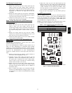
NOTE: An LED (light--emitting diode) indicator is provided on
the control board to monitor operation. The control board is
located by removing the burner access panel (see Fig. 19). During
normal operation, the LED is continuously on.
Step 3 — Start--up Heating and Make Adjust-
ments
UNIT COMPONENT DAMAGE HAZARD
Failureto follow this caution may resultin damage to theunit
being installed.
Completethe required procedures given in thePre--Start--Up
section before starting the unit. Do not jumper any safety
devices when operating the unit.
!
CAUTION
Complete the required procedures given in the Pre--Start--Up
section before starting the unit. Do not jumper any safety devices
when operating the unit. Make sure that burner orifices are
properly aligned. Unstable operation my occur when the burner
orifices in the manifold are misaligned.
Follow the lighting instructions on the heating section operation
label (located on the inside of the control access panel) to start the
heating section.
NOTE: Make sure that gas supply has been purged, and that all
gas piping has been checked for leaks.
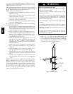
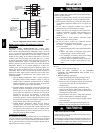
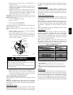
Pipe Plug
Manifold
A07679
Fig. 11 -- Burner Assembly
48EZ --A