


17
4. Divide number of seconds in Step 3 into 3600 (number of
seconds in one hr).
5. Multiply result of Step 4 by the number of cubic feet (cu ft)
shown for one revolution of test dial to obtain cubic feet (cu
ft) of gas flow per hour.
6. Multiply result of Step 5 by Btu heating value of gas to
obtain total measured input in Btuh. Compare this value
with heating input shown in Table 3 (Consult the local gas
supplier if the heating value of gas is not known).
EXAMPLE: Assume that the size of test dial is 1 cu ft, one
revolution takes 32 sec, and the heating value of the gas is 1050
Btu/ft
3
. Proceed as follows:
1. 32 sec. to complete one revolution.
2. 3600 ÷ 32 = 112.5.
3.112.5x1=112.5ft
3
of gas flow/hr.
4. 112.5 x 1050 = 118,125 Btuh input.
If the desired gas input is 115,000 Btuh, only aminor change in the
manifold pressure is required.
Observe manifold pressure and proceed as follows to adjust gas
input:
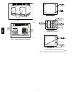
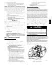
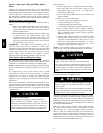
1. Remove regulator cover screw over plastic adjustment
screw on gas valve (See Fig. 13).
2. Turn plastic adjustment screw clockwise to increase gas
input, or turn plastic adjustment screw counterclockwise to
decrease input (See Fig. 13). Manifold pressure must be
between 3.2 and 3.8 IN. W.C.
REGULATOR
COVER SCREW
ADJUSTMENT
SCREW
REGULATOR SPRING
(PROPANE - WHITE)
NATURAL - SILVER)
GAS PRESSURE
REGULATOR
ADJUSTMENT
MANIFOLD
PRESSURE TAP
INLET
PRESSURE TAP
ON/OFF SWITCH
PLASTIC
(
A07751
Fig. 13 -- Single--Stage Gas Valve
FIRE AND UNIT DAMAGE HAZARD
Failure to follow this warning could result in personal
injury or death and/or property damage.
Unsafe operation of the unit may result if manifold pressure
is outside this range.
!
WARNING
3. Replace regulator cover screw on gas valve (See Fig. 13).
4. Turn off gas supply to unit. Remove manometer from
pressure tap and replace pipe plug on gas valve. (See Fig.
11.) Turn on gas to unit and check for leaks.
Measure Manifold Pressure (Propane Units)
Refer to propane kit installation instructions for properly checking
gas input.
NOTE: For installations below 2,000 ft (610 m), refer to the unit
rating plate for proper propane conversion kit. For installations
above2,000 ft (610 m), contact your distributor for proper propane
conversion kit.
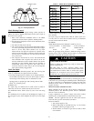
Check Burner Flame
With control access panel (see Fig. 19) removed, observe the unit
heating operation. Watch the burner flames to see if they are light
blue and soft in appearance, and that the flames are approximately
the same for each burner. Propane will have blue flame (See Fig.
12). Refer to the Maintenance section for information on burner
removal.
Normal Operation
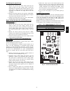
An LED (light--emitting diode) indicator is provided on the
integrated gas unit controller (IGC) to monitor operation. The IGC
is located by removing the control access panel (see Fig. 19).
During normal operation, the LED is continuously on (See Table 5
for error codes).
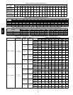
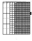
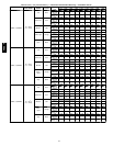
Airflow and Temperature Rise
The heating section for each size unit is designed and approved for
heating operation within the temperature--rise range stamped on the
unit rating plate.
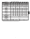
Table 10 shows the approved temperature rise range for each
heating input, and the air delivery cfm at various temperature rises
for a given external static pressure. The heating operation airflow
must produce a temperature rise that falls within the approved
range.
Refer to Indoor Airflow and Airflow Adjustments section to adjust
heating airflow when required.
Limit Switches
Normally closed limit switch (LS) completes the control circuit.
Should the leaving--air temperature rise above the maximum
allowable temperature, the limit switch opens and the control
circuit “breaks.” Any interruption in the control circuit instantly
closes the gas valve and stops gas flow to the burners. The blower
motor continues to run until LS resets.
When the air temperature at the limit switch drops to the
low--temperature setting of the limit switch, the switch closes and
completes the control circuit. The direct--spark ignition system
cycles and the unit returns to normal heating operation.
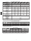
Table 5 – LED Indications
STATUS CODE LED INDICATION
Normal Operation
2
On
No Power or Hardware Failure Off
Limit Switch Fault 2 Flashes
Flame Sense Fault 3 Flashes
Four Consecutive Limit Switch Faults 4 Flashes
Ignition Lockout Fault 5 Flashes
Pressure Switch Fault 6 Flashes
Rollout Switch Fault 7 Flashes
Internal Control Fault 8 Flashes
Temporary 1 hr auto reset
1
9 Flashes
NOTES:
1.This code indicatesan internal processor fault that will reset itself in one
hr. Fault can be causedby stray RF signalsin the structure orn earby. This
isa UL requirement.
2.LED indicatesacceptable operation. Do notchangeignition control
board.
3. When W is energizedthe burnerswill remain on for aminimumof 60 sec.
4.IfmorethanoneerrormodeexiststheywillbedisplayedontheLEDin
sequence.
Rollout Switch
The function of the rollout switch is to close the main gas valve in
the event of flame rollout. The switch is located above the main
burners. When the temperature at the rollout switch reaches the
maximum allowable temperature, the control circuit trips, closing
the gas valve and stopping gas flow to the burners. The indoor
(evaporator) fan motor (IFM) and induced draft motor continue to
run until switch is reset. The IGC LED will display FAULT CODE
7.
48EZ --A