


35
building, route the high tap to atmosphere and the low tap to
building air.
Step 12 — Install All Accessories — After all the
factory-installed options have been adjusted, install all field-
installed accessories. Refer to the accessory installation instruc-
tions included with each accessory.
The 48A Series units have a large number of factory-
installed options which were previously available only as
accessories. Some of the available options can also be installed
in the field if needed. In most cases the units have been
pre-wired so that the accessories can be easily installed.
Instructions are shipped with each accessory. Configuration of
the controls for these accessories as well as the factory-installed
options can be found in the Controls, Start-Up, Operation,
Service and Troubleshooting Book. The following is a list of
some of the common accessories:
• Thermostats and space temperature sensors
• LP (liquid propane) conversion kit
• Accessory barometric relief damper
• Accessory power exhaust
• Non-modulating to modulating power exhaust
• Condenser coil hail guards
• Outdoor humidity sensor (used for economizer enthalpy
changeover)
• Return air humidity sensors (used for economizer
differential enthalpy changeover)
• Return air smoke detector
• Controls expansion module (used for interface to build-
ing management systems, not typically needed on
system with the Carrier Comfort Network
®
[CCN] sys-
tem)
• Plugged filter sensor
• Motormaster® V low ambient head pressure control
Step 13 — Field Modifications
DUCTWORK
Bottom Return Units (48AJ and AK) Field-Modified for
Side Return — The 48AJ and AK units with bottom return air
connections may be field-modified to accommodate side return
air connections.
Conversion to horizontal return requires that the bottom
return openings of the unit must be sealed with airtight panels
capable of supporting the weight of a person. The return
ductwork connection locations on the side of the unit are higher
than normal (31-in. high). Unit-mounted power exhaust or
barometric relief cannot be used because of return air ductwork
will cover the power exhaust or barometric relief installation
locations. Power exhaust or barometric relief may be installed
in the return air ductwork.
To convert the unit, perform the following:
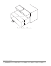
1. Seal the bottom return openings of the unit with airtight
panels capable of supporting the weight of a person.
2. Remove the panels located below the economizer
outdoor-air dampers. These openings will be used for the
return-air ductwork. There are 2 panels on 48AJ,AK020-
050 units. There are 3 panels on 48AJ,AK051 and 060
and units. These openings are normally used for power
exhaust or barometric relief.
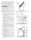
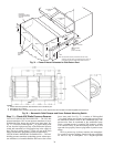
3. Run the return air ductwork up to the openings. One
single duct is recommended to connect to the unit over
the return air openings. See Fig. 34. The return duct must
incorporate a minimum
3
/
4
-in. flange for connection to
the unit cabinet. The unit does not have duct flanges for
this conversion.
Side Supply and Return Units (48AW,AY) with Field-
Installed Power Exhaust in Return Duct — Space must be
available in the return duct to mount the power exhaust fan
(gravity relief) modules. Dimensions and suggested locations
are shown in Fig. 34. These instructions are a guideline and not
a comprehensive procedure. The design contractor must pro-
vide some design initiative.
The wiring harness that is provided with the power exhaust
accessory is not long enough for the fan modules to be mount-
ed in the return air duct. Field-supplied wiring must be spliced
into the harness. Use a junction box at each splice. The wiring
may be run in the return duct, or externally in conduit. A ser-
vice access panel will be needed near each power exhaust fan.
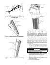
IMPORTANT: Carrier recommends the installation of
field-fabricated wind baffles on all vertically oriented
condenser coils when operating in environments with
prevailing winds of more than 5 MPH and where tem-
peratures drop below 32 F. See the Motormaster
accessory installation guide for instructions.
IMPORTANT: The following section is a guideline and not
a comprehensive procedure to field modify the units. The
installing contractor must provide some design initiative.
Field-conversion is complex and is not recommended.
Units with electric heat must not be converted because of
potential heating mode operating problems.
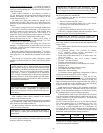
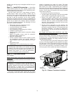
AUXILIARY
CONTROL BOX
PRESSURE TRANSDUCERS
(INSIDE OF PANEL)
Fig. 33 — Pressure Transducer Locations
a48-6976