


34
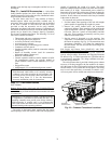
Step 11 — Route VAV Static Pressure Sensors
VAV DUCT PRESSURE TRANSDUCER — The VAV duct
pressure transducer (VAV inverter pressure transducer) is locat-
ed behind the filter access door on the lower inner panel. See
Fig. 33. A section of field-supplied
1
/
4
-in. plastic tubing must
be run from the high pressure tap on the differential pressure
switch and connected to a field-supplied tap in the supply-air
duct. The tap is usually located
2
/
3
of the way out on the main
supply duct. Remove plug button in panel to route tubing.
VAV BUILDING PRESSURE TRANSDUCER — The VAV
building pressure transducer (modulating power exhaust pres-
sure transducer) is located behind the filter access door on the
lower inner panel. See Fig. 33. A section of field-supplied
1
/
4
-in. plastic tubing must be run from the high pressure tap on
the differential pressure switch to the conditioned space. The
pressure tube must be terminated in the conditioned space
where a constant pressure is required. This location is usually
in an entrance lobby so that the building exterior doors will
open and close properly. Remove plug button in panel to route
tubing.
The low pressure tap is factory-routed to the atmosphere.
For a positive-pressure building, route the high tap to building
air and low tap to atmosphere. For a negative-pressure
42.56”
42” MIN.
S/A
R/A
ECONOMIZER
HOOD
ECONOMIZER
HOOD
J BOX
PLENUM RATED
CABLE
(FIELD SUPPLIED)
12.94
(UNIT
OPENING)
NOTE: 020-050 SIZES SHOWN (2 POWER EXHAUST FANS).
SIZES 051 AND 060 HAVE 3 POWER EXHAUST FANS. ALL
UNIT SIZES HAVE THE SAME SIZE POWER EXHAUST.
“END #2”
“END #1”
ALTERNATE
LOCATION
(END)
23.28”
TYP
42.62
TYP
LOCATION
BAROMETRIC RELIEF
OR POWER EXHAUST
“SIDE #2”
23.28”
“SIDE #1”
42.62”
J BOX
R/A
S/A
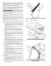
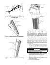
Fig. 31 — Power Exhaust Relocated to Side Return Duct
a48-8244
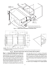
NOTES:
1. Unless otherwise specified, all dimensions are to outside of part.
2. Dimensions are in inches.
3. On 48AW,AY units, accessory barometric relief or power exhaust must be mounted in the field-supplied return ductwork.
Fig. 32 — Barometric Relief Damper and Power Exhaust Mounting Details
a48-3808