


29
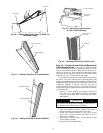
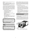
Routing Through Bottom of Unit
— If wiring is brought in
through bottom of unit, use field-supplied watertight conduit to
route power wiring through the 3
1
/
2
-in. diameter hole provided
in the unit basepan.
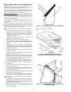
Install conduit connector in unit basepan as shown in
Fig. 4-9. Route power and ground lines through connector to
terminal connections in unit control box as shown on unit
wiring diagram and Fig. 19.
Use strain relief going into control box through 3
5
/
8
-in.
diameter hole provided. After wires are in unit control box,
connect to power terminal block (see Power Wiring section on
page 20).
Low-voltage wiring must be run in watertight conduit from
the basepan to control box and through
7
/
8
-in. diameter hole
provided in bottom of unit control box. Field-supplied strain
relief must be used going into the box. After wiring is in
control box, make connections to proper terminals on terminal
blocks (see Field Control Wiring section on this page).
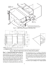
Routing Through Side of Unit
— Route power wiring in
field-supplied watertight conduit into unit through 2
1
/
2
-in. (siz-
es 020-035) or 3-in. (sizes 036-060) hole.
Use field-supplied strain relief going into control box
through 3
5
/
8
-in. diameter hole provided. After wires are in unit
control box, connect to power terminal block (see Power Wir-
ing section on page 20).
Bring low-voltage control wiring through the
7
/
8
-in. diame-
ter hole provided in the condenser section side post. Use strain
relief going into
7
/
8
-in. diameter hole in bottom of unit control
box.
After wiring is in control box, make connection to proper
terminals on terminal blocks (see Field Control Wiring section
below).
Affix crankcase heater sticker (located in the installers
packet) to unit disconnect switch.
Voltage to compressor terminals during compressor operation
must be within the voltage range indicated on the unit name-
plate. Phases must be balanced within 2%.
Use the formula in Tables 8A and 8B to determine the per-
centage of voltage imbalance.
Unit failure as a result of operation on improper line voltage
or excessive phase imbalance constitutes abuse and may cause
damage to electrical components.
For transformer 1 move the black wires connected to termi-
nal H2 and connect it to terminal H3.
For transformers 2-4, that are used for the 24-volt control
circuits, connect as follows:
1. Remove cap from red (208 v) wire.
2. Remove cap from spliced orange (230 v) wire. Discon-
nect orange wire from black unit power wire.
3. Cap orange wire.
4. Splice red wire and black unit power wire. Cap wires.
If the unit is equipped with the optional convenience outlet
connect the yellow wire to H2 on transformer 5.
FIELD CONTROL WIRING — The 48A Series units sup-
port a large number of control options that can impact the field
control wiring.
The control options that the unit can provide relate to the
following parameters:
• CV (constant volume), VAV (variable air volume),
VVT
®
(variable volume variable temperature) or
Carrier TEMP system control operation.
• Stand-alone with a thermostat (CV) or with a space sen-
sor (CV and VAV)
• Network application with CCN (Carrier Comfort
Network
®
) or other networks
• Demand ventilation with CO
2
sensor
• Economizer and economizer with changeover control
• Staged gas heat
• Building and duct static pressure control
• Fire shutdown and smoke control
• Diagnostics and monitoring
For constant volume applications a thermostat (T-Stat) or
space temperature sensor (SPT) will be required.
T-STAT (Conventional Thermostat)
— Unit can be con-
trolled with a Carrier-approved accessory electro-mechanical
or electronic thermostat that has two stages of cooling, two
stages of heating control and an output for indoor fan control. It
may also include time of day scheduling or use the scheduling
routines built into the ComfortLink™ controls.
Install thermostat according to the installation instructions
included with accessory thermostat and the unit wiring dia-
grams. Locate thermostat assembly on a solid interior wall in
the conditioned space to sense average temperature.
Route thermostat cable or equivalent single leads of colored
wire from subbase terminals through conduit into unit to low-
voltage connection in the main control box. For thermostat
TB4 connections see Fig. 20.
NOTE: For wire runs up to 50 ft, use no. 18 AWG (American
Wire Gage) insulated wire (35 C minimum). For 50 to 75 ft,
use no. 16 AWG insulated wire (35 C minimum). For over
75 ft, use no. 14 AWG insulated wire (35 C Minimum). All
wire larger than no. 18 AWG cannot be directly connected at
the thermostat and will require a junction box and splice at the
thermostat. Set heat anticipator settings as follows:
Settings may be changed slightly to provide a greater degree of
comfort for a particular installation.
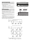
IMPORTANT: The VAV (variable air volume) units use
variable frequency drives, which generate and can radiate
radio frequency energy. If units are not installed and used
in accordance with these instructions, they may cause radio
interference. They have been tested and found to comply
with limits of a Class A computing device as defined by
FCC (Federal Communications Commission) regulations,
Subpart J of Part 15, which are designed to provide reason-
able protection against such interference when operated in
a commercial environment.
WARNING
The unit must be electrically grounded in accordance with
local codes and NEC ANSI/NFPA 70 (National Fire
Protection Association). Electrical shock could cause per-
sonal injury.
IMPORTANT: If the supply voltage phase imbalance is
more than 2%, contact your local electric utility company
immediately.
IMPORTANT: On 208/230-v units, transformers 1-5 are
wired for 230-v. If 208/230-v unit is to be run with 208-v
power supply, the transformers must be rewired as follows:
IMPORTANT: BE CERTAIN UNUSED WIRES ARE
CAPPED. Failure to do so may damage the transformers.
SIZE
STAGE 1
(W1) ON
STAGE 2
(W1 and W2) ON
020-050 0.24 0.13
051, 060 0.36 0.13