


20
Size gas-supply piping for 0.5-in. wg maximum pressure
drop. Do not use supply pipe smaller than unit gas connection.
OPTIONAL STAGED GAS UNITS — See Table 7 for staged
gas information. Staging pattern is selected during controls
start-up.
For complete information and service instructions for
Staged Gas Control Units, see Control Operation and Trouble-
shooting literature.
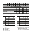
Table 7 — 48A Series Staged Gas Control
Step 8 — Make Electrical Connections
POWER WIRING — Units are factory wired for the voltage
shown on the unit nameplate.
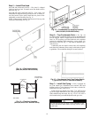
Provide a unit safety disconnect switch in the main power
supply to each unit (see Fig. 19). Select switch size and mount-
ing location in accordance with applicable local codes or
National Electrical Code (NEC). If combining the functions of
safety disconnect with maximum overcurrent protection
(MOCP) fuses (“fused disconnect”), coordinate safety switch
size with MOCP size data as marked on unit informative plate.
Unit may be equipped with optional factory-installed non-
fused disconnect switch (see Fig. 19). Provide maximum
overcurrent protection devices (fuses or HACR breakers, per
local codes) in branch circuit wiring remote from unit. Observe
requirements of NEC Article 440. Install service switch
upstream of remote fuses if required.
The main power terminal block is suitable for use with
aluminum or copper wire. See Fig. 19. Units have circuit
breakers for compressors, fan motors, and control circuit. The
unit must be electrically grounded in accordance with local
codes, or in absence of local codes, with NEC, ANSI C1-latest
year.
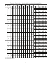
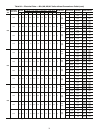
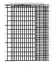
FIELD POWER SUPPLY — Unit is factory wired for volt-
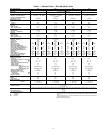
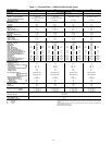
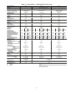
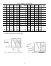
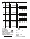
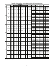
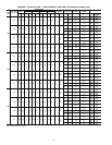
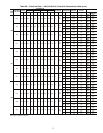
age shown on unit nameplate. See Tables 8A and 8B for elec-
trical data.
Field wiring can be brought into the unit from bottom
(through basepan and roof curb) or through side of unit (corner
post next to control box).
A 3
1
/
2
-in. NPT coupling for field power wiring and a
3
/
4
-in.
NPT coupling for 24-v control wiring are provided in basepan.
In the side post, there are two 2
1
/
2
-in. (48A020-035) or 3-in.
(48A036-060) knockouts for the field power wiring. See
Fig. 4-9. If control wiring is to be brought in through the side of
unit, a
7
/
8
-in. diameter hole is provided in the condenser side
post next to the control box.
Do not route control wiring in the same conduit as power
wiring.
If disconnect box is mounted to corner post, be careful not
to drill or screw into the condenser coil.
IMPORTANT: Natural gas pressure at unit gas connection
must not be less than 5 in. wg or greater than 13.5 in. wg.
MODEL NUMBER POSITION
NUMBER OF
STAGES
HEAT SIZE
5 6,7,8
S
020
025
027
030
035
036
040
041
050
5 stages
Low
T
035
036
040
041
050
High
T
020
025
027
030
7 stages High
T 051,060 9 stages High
S 051,060 11 stages Low
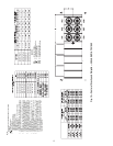
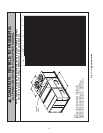
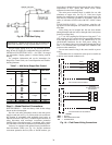
Fig. 18 — Field Gas Piping
a48-2524
FIELD SUPPLIED
DISCONNECT PER NEC
FIELD
POWER
SUPPLY
11
21
22
23
13
12
TB1
EQUIP GND
FIELD POWER WIRING
11
21
22
23
13
12
GND
OPTIONAL
FACTORY-INSTALLED
DISCONNECT
FIELD-INSTALLED DISCONNECT
FACTORY-INSTALLED DISCONNECT
LEGEND
GND — Ground
NEC — National Electrical Code
TB — Terminal Block
Fig. 19 — Field Power Wiring Connections
a48-6977