


31
T58 Communicating Thermostat
— Carrier also has a fully
communicating thermostat which, if used, will be wired to the
CCN communication connections on TB3 as described in the
Carrier Comfort Network
®
Interface section below.
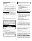
Carrier Comfort Network Interface
— The rooftop units can
be connected to the CCN system. The communication bus
wiring is supplied and installed in the field. Wiring consists of
shielded, 3-conductor cable with drain wire. The system
elements are connected to the communication bus in a daisy
chain arrangement. The positive pin of each system element
communication connector must be wired to the positive pins of
the system element on either side of it, the negative pins must be
wired to the negative pins, and the signal pins must be wired to
signal ground pins. Wiring connections for CCN should be
made at the TB3 terminal block using the screw terminals. The
TB3 board also contains an RJ14 CCN plug that can be used to
connect a field service computer or other CCN device tempo-
rarily. There is also an RJ14 LEN (local equipment network)
connection that is used to connect a Navigator
™
device or
download software.
Conductors and drain wire must be 20 AWG minimum
stranded, tinned copper. Individual conductors must be insulat-
ed with PVC, PVC/nylon, vinyl, Teflon, or polyethylene. An
aluminum/polyester 100% foil shield and an outer jacket of
PVC, PVC/nylon, chrome vinyl, or Teflon with a minimum
operating temperature range of –20 C to 60 C (–4 F to 140 F) is
required. Table 9 lists cables that meet the requirements.
Table 9 — CCN Connection Approved Shield Cable
Table 10 — Color Code Recommendations
If a cable with a different color scheme is selected, a similar
color code should be adopted for the entire network. At each
system element, the shields of the communication bus cables
must be tied together. If the communication bus is entirely
within one building, the resulting continuous shield must be
connected to a ground at one point only. If the communication
bus cable exits from one building and enters another, the
shields must be connected to grounds at the lightning suppres-
sor in each building where the cable enters or exits the building
(one point per building only).
To connect the unit to the network:
1. Turn off power to the control box.
2. Cut the CCN wire and strip the ends of the red (+), white
(ground), and black (–) conductors. (If a different net-
work color scheme is used, substitute appropriate colors.)
3. Remove the 3-pin male plug from the base control board
in the main control box, and connect the wires as follows:
a. Insert and secure the red (+) wire to terminal 1 of
the 3-pin plug.
b. Insert and secure the white (ground) wire to termi-
nal 2 of the 3-pin plug.
c. Insert and secure the black (–) wire to terminal 3 of
the 3-pin plug.
4. Insert the plug into the existing 3-pin mating connector on
the base module in the main control box.
VAV Units with Heat
— For variable air volume units that
will use heat, the variable air volume terminals should be
interlocked with the unit at TB5 terminals 1 and 2.
Demand Ventilation
— The unit can be equipped with a CO
2
sensor for use in demand ventilation. This can be factory
supplied and will be mounted in the return duct. It can also be
field supplied and mounted in the return duct or in the space.
Connect the field-installed 4 to 20 mA sensor to TB5 terminal
6 and 7. Do not remove the factory-installed 182-ohm resistor.
If an outdoor air quality sensor is used then it should be
wired to terminal 11 and 12 on TB6. This will require the use
of the optional controls expansion module.
Remote IAQ Override
— If the control is being used with non
Carrier building management system it supports the use of the
remote IAQ override switch. This should be connected to
TB6 terminal 13 and 14. Use of this will require the optional
controls expansion module.
Remote Economizer Position Control
— The ComfortLink™
controls will normally control the position of the economizer,
but it can also support field control of the economizer position
through a 4 to 20 mA signal. If this is used it should be con-
nected to TB5 terminal 6 and 7. If the signal is a 4 to 20 mA
signal then leave the 182-ohm resistor in place.
Remote Economizer Enable
— If the control is being used
with other building management systems and the system will
control the enabling and disabling of the economizer free cool-
ing, this switch input can be connected to TB6 terminals 1 and
2. Note that the controls also support integrated economizer
changeover using outdoor dry bulb, differential dry bulb,
outdoor enthalpy and differential enthalpy.
Remote Occupancy Switch
— For interface to other building
management systems the control also supports a switch input
for remote occupancy signals. This wiring should be connected
to terminal TB6 terminal 1 and 3.
Remote Economizer Minimum Position Control
— If the
ComfortLink control is controlling the economizer, but a remote
minimum position is required, then an external 100K potentiom-
eter can be connected to TB5 terminal 6 and 7. Remove the
factory-installed 182-ohm resistor.
Smoke Sensor Interface
— The ComfortLink control includes
an optional factory-installed return air smoke detector. Remote
alarm circuits can be wired to TB5 terminal 8 and 9.
Fire Shutdown and Smoke Control
— The control supports
interface to fire and smoke control systems and allows for the
following system overrides from remote switch inputs.
• Fire Shutdown — Connect to TB6 terminals 8 and 9.
• Smoke Pressurization — Connect to TB6 terminal 12
and 13. This requires the use of the optional controls
expansion module.
• Smoke Evacuation — Connect to TB6 terminal 12 and
14. This requires the use of the optional controls expan-
sion module.
• Smoke Purge — Connect to TB6 terminal 12 and 15.
This requires the use of the optional controls expansion
module.
Demand Limiting
— The control can also be used with demand
limiting control from remote building management systems. If a
two stage system is going to be used with Redline Limiting
where the machine is not allowed to increase load and Load Shed
where the load is decreased to a configurable limit in capacity
then these can be connected to TB6 terminals 4 and 5 and 5 and
6. This requires use of the controls expansion module.
MANUFACTURER CABLE PART NO.
Alpha 2413 or 5463
American A22503
Belden 8772
Columbia 02525
IMPORTANT: When connecting to CCN communi-
cation bus to system elements, use color coding
system for the entire network to simplify installation
and checkout. See Table 10.
SIGNAL TYPE
CCN BUS CONDUCTOR
INSULATION COLOR
CCN PLUG PIN
NO.
Positive (+) RED 1
Ground WHITE 2
Negative (–) BLACK 3