


33
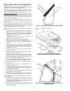
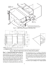
Step 10 — Position Power Exhaust/Barometric
Relief Damper Hood — All units are shipped with the
hoods folded inside the unit in a shipping position. For 48AJ,
and AK units the hood must be tilted out once the unit is in-
stalled. On 48AW, AY units, (designed for horizontal supply
and return) the assemblies will have to be relocated to return
ductwork. See Fig. 31 for dimensions and details.
All electrical connections have been made and adjusted at
the factory. The power exhaust blowers and barometric relief
dampers are shipped assembled and tilted back into the unit for
shipping. Brackets and extra screws are shipped in shrink wrap
around the dampers. If ordered, each unit will have 4
(48AJ,AK,AW,AY020-050 units) or 6 (48AJ,AK,AW,AY051
and 060 units) power exhaust blowers and motors or baromet-
ric relief dampers.
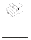
1. Remove 9 screws holding each damper assembly in
place. See Fig. 32. Each damper assembly is secured with
3 screws on each side and 3 screws along the bottom.
Save screws.
2. Pivot each damper assembly outward until edges of
damper assembly rest against inside wall of unit.
3. Secure each damper assembly to unit with 6 screws
across top (3 screws provided) and bottom (3 screws
from Step 1) of damper.
4. With screws saved from Step 1, install brackets on each
side of damper assembly.
5. Remove tape from damper blades.
CAUTION
Be careful when tilting blower assembly. Hoods and blow-
ers are heavy and can cause injury if dropped.
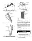
MOUNTING ANGLE
FILTER TRACK
ASSEMBLY
Fig. 29 — Mounting Angle Attached
to Filter Track Assembly
a48-8499
BLACK SEAL STRIP
(CENTERED)
FILTER COVER
Fig. 30 — Attaching Seal Strip to Filter Cover
48-1110
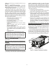
HOOD TOP
HOOD SIDE
CROSS MEMBER
GRAY FOAM STRIP
Fig. 26 — Adding Seal Strip to Back of Hood Top
Mounting Flange
Fig. 27 — Adding Foam Strip to Cross Member
48-1104
48-1105
BLOCKOFF BAFFLE
GRAY FOAM STRIP
Fig. 28 — Adding Seal Strip to Block-Off Baffle
a48-4328