


9
f. Run the FR cable through the
1
/
2
-in. connector of
the MMV enclosure (do not tighten connector
screws at this time). Connect black wire to MMV
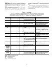
terminal 2 and red wire to MMV terminal 1, 13A,
or 13C (see Table 4). Place 1 small varnish cloth
38C24601 around both cables at the point they
enter the
1
/
2
-in. connector. Tighten down connector
screws being careful not to damage the cables.
8. Bundle excess wire and dress harnesses with wire ties.
9. Re-attach control box, MMV enclosure, and cable tray
covers.
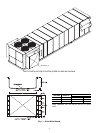
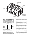
48/50P070-100 UNITS — For 48/50P070-075 units, two
Motormaster controls are used to control two independent out-
door-fan motors (OFM). The refrigerant circuit-A Motormas-
ter
®
controlled OFM is the no. 3 OFM. The refrigerant circuit-
B Motormaster controlled OFM is the no. 1 OFM (see Fig. 3).
The no. 2 and 4 OFMs are controlled by the ComfortLink™
head pressure control routine.
For 48/50P090-100 units, the two Motormaster controls are
used to control two independent outdoor-fan motors. The re-
frigerant circuit-A Motormaster controlled OFM is the no. 6
OFM. The refrigerant circuit-B Motormaster controlled OFM
is the no. 2 OFM (see Fig. 3). The no. 1, 3, 4, and 5 OFMs are
controlled by the ComfortLink head pressure control routine.
Use the following procedure to mount and connect the
MMV controllers to this unit:
1. Disconnect power to the unit. Lockout and tag power dis-
connect.
2. Remove control box covers.
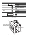
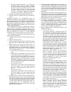
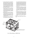
3. Remove fan decks to gain access to each circuit’s respec-
tive Motormaster controlled OFM, as shown in Fig. 9 and
10.
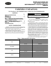
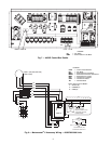
4. Mount accessory fuse blocks HY11UT035 (label 1 as
MMF-A and the other as MMF-B) and fan relay bases
HN79KK035 (label 1 as FR-A and the other as FR-B) in-
side control box as shown in Fig. 7. Secure components
with ½-in. sheet metal screws.
a. Insert fuses into fuse blocks and relays into relay
bases.
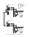
b. Install harnesses 48EJ402454 from load side of
CCB (control circuit breaker terminals 21, 22, 23)
to line side of MMF-A and MMF-B fuse blocks as
shown in Fig. 11. Note that it may be easier to
pickup the load side of CCB from the ¼-in. male
quick connect terminals on the line side (terminals
11, 12, 13) of the OFC contactors (see power sche-
matic on control box door).
c. For 070 and 075 units:
Connect FR-A coil to OFC3 coil and FR-B coil to
OFC1 coil using the 72 in. long 16 gage white and
gray wires (stripped end goes to FR) as shown in
Fig. 11.
For 090 and 100 units:
Connect FR-A coil to OFC3 coil and FR-B coil to
OFC2 coil using the 72 in. long 16 gage white and
gray wires (stripped end goes to FR) as shown in
Fig. 11.
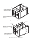
5. Mount the MMV controller enclosures 30RA500381on
the bulkhead, as shown in Fig. 9 (sizes 070 and 075) and
Fig. 10. (sizes 090 and 100) using the mounting brackets
50EJ500656 installed on the enclosures (label 1 as MMV-
A and the other as MMV-B). Remove the enclosure cov-
ers and install the ½-in. HW60EA001 and 1-in.
HW60HH006 connectors in the holes in the lower right
hand side of the enclosures.
6. Connect transducers HK05ZZ001 to the liquid line ser-
vice Schrader ports, located under the V-coils of the con-
denser fan sections, of refrigerant circuit A and B. Circuit
A is the one closest to the Indoor Fan Motor section, and
circuit B is the one closest to the control box, (label cir-
cuit A transducer as MMPT-A and circuit B transducer as
MMPT-B).
7. Plug transducer cables 48EJ403240 into transducers (la-
bel stripped end of circuit A cable as MMPT-A and the
stripped end of circuit B cable as MMPT-B). Run cables
along inside of unit base rail and up the corner post to the
MMV enclosures, as shown in Fig. 9 and 10.
8. Run MMPT-A cable through
1
/
2
-in. connector of MMV-
A enclosure, and MMPT-B cable through
1
/
2
-in. connec-
tor of MMV-B enclosure (do not tighten connector
screws at this time). Connect red, green, and black wires
to MMV-A and MMV-B terminals 6, 5, and 2 as shown
in Fig. 11. Terminate drain wire of transducer cables un-
der one of the lower MMV mounting screws.
9. Make remaining electrical connections to MMV-A and
MMV-B (see Fig. 11).
a. For 070 and 075 units:
In the main control box, disconnect black, red,
blue, and green wires from load side (terminals 21,
22, 23) of OFC1 and OFC3 contactors (label cable
from OFC1 as OFM1 and cable from OFC3 as
OFM3). Pull wires out through the hole in the bot-
tom of the control box and run them up the corner
post to the opening of the cable tray on the side of
the control box, as shown in Fig. 9. Run the cable
through the wire tray to the MMV enclosures.
Run the OFM1 cable through the 1-in. connector
of the MMV-B enclosure (do not tighten connector
screws at this time). Remove ring terminals from
black, red, and blue wires and strip insulation back
3/8-in. Connect black, red, and blue wires to
MMV-B terminals T1, T2, and T3. Connect green
ground wire to MMV-B ground screw.
Run OFM3 cable through 1-in. connector of
MMV-A enclosure (do not tighten connector
screws at this time). Remove ring terminals from
black, red, and blue wires and strip insulation back
3
/
8
-inch. Connect black, red, and blue wires to
MMV-A terminals T1, T2, and T3. Connect green
ground wire to MMV-B ground screw.
For 090 and 100 units:
In Main Control box, disconnect black, red, blue,
and green wires from load side (terminals 21, 22,
23) of OFC2 and OFC3 contactors (label cable
from OFC2 as OFM2 and cable from OFC3 as
OFM3). Pull wires out through the hole in the bot-
tom of the control box and run them up the corner
post to the opening of the cable tray on the side of
the control box, as shown in Fig. 10. Run the cable
through the wire tray to the MMV enclosures.
Run the OFM2 cable through the 1-in. connector
of the MMV-B enclosure (do not tighten connector
screws at this time). Remove ring terminals from
black, red, and blue wires and strip insulation back
3
/
8
-in. Connect black, red, and blue wires to MMV-
B terminals T1, T2, and T3. Connect green ground
wire to MMV-B ground screw.
Run OFM6 cable through 1-in. connector of
MMV-A enclosure (do not tighten connector
screws at this time). Remove ring terminals from
black, red, and blue wires and strip insulation back
3/8-in. Connect black, red, and blue wires to
MMV-A terminals T1, T2, and T3. Connect green
ground wire to MMV-B ground screw.