


13
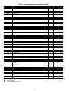
Drive Programming — Table 5 shows all program pa-
rameters for each of the operating modes. Refer to Trouble-
shooting section before attempting to change programming in
the Motormaster V control.
TO ENTER PASSWORD AND CHANGE PROGRAM
VALUES:
1. Press MODE.
2. The display will read “00” and the upper right-hand deci-
mal point will be blinking. This will activate the PASS-
WORD prompt (if the password has not been disabled).
3. Use the UP and DOWN buttons to scroll to the password
value (the factory default password is “111”) and press
the MODE button. Once the correct password value is en-
tered, the display will read “P01”, which indicates that the
PROGRAM mode has been accessed at the beginning of
the parameter menu (P01 is the first parameter).
NOTE: If the display flashes “Er”, the password was incorrect,
and the process to enter the password must be repeated.
4. Press MODE to display present parameter setting. The
upper right decimal point blinks. Use UP and DOWN
buttons to scroll to the desired parameter number.
5. Once the desired parameter number is found, press the
MODE button to display the present parameter setting.
The upper right-hand decimal point will begin blinking,
indicating that the present parameter setting is being dis-
played. Use the UP and DOWN buttons to change set-
ting. Press MODE to store new setting.
6. Press MODE to store the new setting and also exit the
PROGRAM mode. To change another parameter, press
the MODE button again to re-enter the PROGRAM
mode (the parameter menu will be accessed at the param-
eter that was last viewed or changed before exiting). If the
MODE button is pressed within two minutes of exiting
the PROGRAM mode, the password is not required to ac-
cess the parameters.
7. After two minutes, the password must be entered in order
to access the parameters again.
TO CHANGE PASSWORD — Enter the current password
then change P44 to the desired password.
TO RESET FACTORY DEFAULTS — To recognize a fac-
tory reset, the MMV controller must see a change in P48.
1. Cycle power from Motormaster
®
V control.
2. Enter PROGRAM mode by entering password.
3. Scroll to P48 by using UP and DOWN buttons and then
press MODE. One of the 12 mode numbers will appear.
(Modes 1, 2 and 4 are used for these units.)
4. Restore factory defaults by changing the value in P48 us-
ing UP and DOWN buttons and then storing the value by
pressing MODE.
5. Press MODE again to re-display the value of P48.
6. Change the value of P48 to the desired factory default
mode (see Table 5) using UP and DOWN buttons then
press MODE. The Motormaster V control is now restored
to factory settings.
TROUBLESHOOTING
Troubleshooting the Motormaster V control requires a com-
bination of observing system operation and VFD display
information.
If the liquid line pressure is above the set point and the VFD
is running at full speed, this is a normal condition. The fan
CANNOT go any faster to maintain set point.
If the VFD is not slowing down even though liquid line
pressure is below set point, the VFD could be set for manual
control or the control may be receiving faulty pressure trans-
ducer output. Corrective action would include:
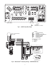
• Check that VDC signal between TB5 and TB2 is
between 0.5 v and 4.5 v.
• Restore VFD to automatic control.
• Change parameter P05 back to correct value shown in
Table 5.
The MMV control also provides real time monitoring of
key inputs and outputs. The collective group is displayed
through parameters P50 to P56 and all values are read only.
These values can be accessed without entering a password.
Press MODE twice and P50 will appear.
Press MODE again to display value.
To scroll to P51-P56 from P50, use UP and DOWN buttons
then press MODE to display the value.
• P50: FAULT HISTORY — Last 8 faults
• P51: SOFTWARE version
• P52: DC BUS VOLTAGE — in percent of nominal.
Usually rated input voltage x 1.4
• P53: MOTOR VOLTAGE — in percent of rated output
voltage
• P54: LOAD — in percent of drives rated output current
• P55: VDC INPUT — in percent of maximum input:
100% will indicate full scale which is 5 v
• P56: 4-20 mA INPUT — in percent of maximum input.
20% = 4 mA, 100% = 20 mA
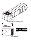
NOTE: The Motormaster V transducer is attached to circuit A.
If circuit A compressor power is interrupted (overload, high
pressure cutout, etc.) the outdoor fans will operate at a reduced
speed resulting from erroneous low pressure readings. This
process may cause a high pressure safety cutout on circuit B
compressor. If only circuit B is capable of operating for a tem-
porary period of time because of a circuit A problem, the trans-
ducer will have to be moved to the circuit B service port until
circuit A can be repaired. Once the problem is repaired, move
the transducer back to circuit A for proper unit operation.
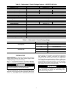
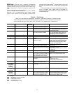
Fault Lockout — If a fault lockout (LC) has occurred,
view the fault history in P50 to find the last fault. Once P50 is
displayed, use the arrow buttons to scroll through the last 8
faults. Any current faults or fault codes from the fault history
can be analyzed using Table 6.
TO DISABLE AUTOMATIC CONTROL MODE AND
ENTER MANUAL SPEED CONTROL:
1. Change P05 to ‘01- keypad’.
2. Push UP and DOWN arrow button to set manual speed.
3. Set P05 to proper value to restore automatic control ac-
cording to Table 5.
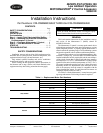
TO PROVIDE MANUAL START/STOP CONTROL — With
power removed from VFD, remove start command jumper and
install a switch between the appropriate start terminals as re-
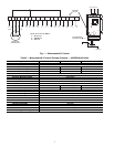
quired in Table 4.
CAUTION
It is strongly recommended that the user NOT change any
programming without consulting Carrier service personnel.
Unit damage may occur from improper programming.