


10
b. In main control box connect one Motormaster
VFD harness 48ZZ401971 to the load side of
MMF-A (label the opposite end of this harness as
MMF-A) and the other Motormaster VFD har-
nesses 48ZZ401971 to the load side of MMF-B
(label the opposite end of this harness as MMF-B).
Run the harnesses along the bottom of the control
box and out through the hole that the OFM har-
nesses were in. Pull the harnesses out through the
hole in the bottom of the control box and run them
through the opening of the cable tray (in the same
manner as the OFM harnesses).
c. Run the MMF-A cable through 1-in. connector of
MMV-A enclosure (do not tighten connector
screws at this time). Connect L1, L2, and L3 wires
to MMV-A terminals L1, L2, and L3. Connect
green ground wire to MMV-A ground screw. Place
1 large varnish cloth 48DA510141 around both
cables at the point they enter the 1-in. connector.
Tighten down connector screws being careful not
to damage the cables.
d. Run the MMF-B cable through 1-in. connector of
MMV-B enclosure (do not tighten connector
screws at this time). Connect L1, L2, and L3 wires
to MMV-B terminals L1, L2, and L3. Connect
green ground wire to MMV-B ground screw. Place
the other large varnish cloth 48DA510141 around
both cables at the point they enter the 1-in. connec-
tor. Tighten down connector screws being careful
not to damage the cables.
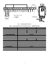
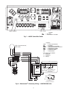
e. In Main Control box connect 1 Motormaster VFD
(variable frequency drive) harness 48ZZ402001 to
the NO (normally open) contact of FR-A (see
Fig. 11) (label the opposite end of this harness as
FR-A) and the other Motormaster VFD harness
48ZZ402001 to the NO contact of FR-B (label the
opposite end of this harness as FR-B). Run the har-
nesses along the bottom of the control box and out
through the hole that the OFM harnesses were in.
Pull the harnesses out through the hole in the bot-
tom of the control box and run them through the
opening of the cable (in the same manner as the
OFM harnesses).
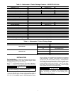
f. Run the FR-A cable through the
1
/
2
-in. connector
of the MMV-A enclosure (do not tighten connector
screws at this time). Connect black wire to MMV-
A terminal 2 and red wire to MMV-A terminal 1,
13A, or 13C (see Table 4). Place 1 small varnish
cloth 38C24601 around both cables at the point
they enter the
1
/
2
-in. connector. Tighten down con-
nector screws being careful not to damage the
cables.
g. Run the FR-B cable through the
1
/
2
-in. connector
of the MMV-B enclosure (do not tighten connector
screws at this time). Connect black wire to MMV-
B terminal 2 and red wire to MMV-B terminal 1,
13A, or 13C (see Table 4). Place the other small
varnish cloth 38C24601 around both cables at the
point they enter the
1
/
2
-in. connector. Tighten down
connector screws being careful not to damage the
cables.
10. Bundle excess wire and dress harnesses with wire ties.
11. Reattach control box, MMV enclosure, and cable tray
covers.
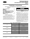
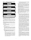
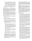
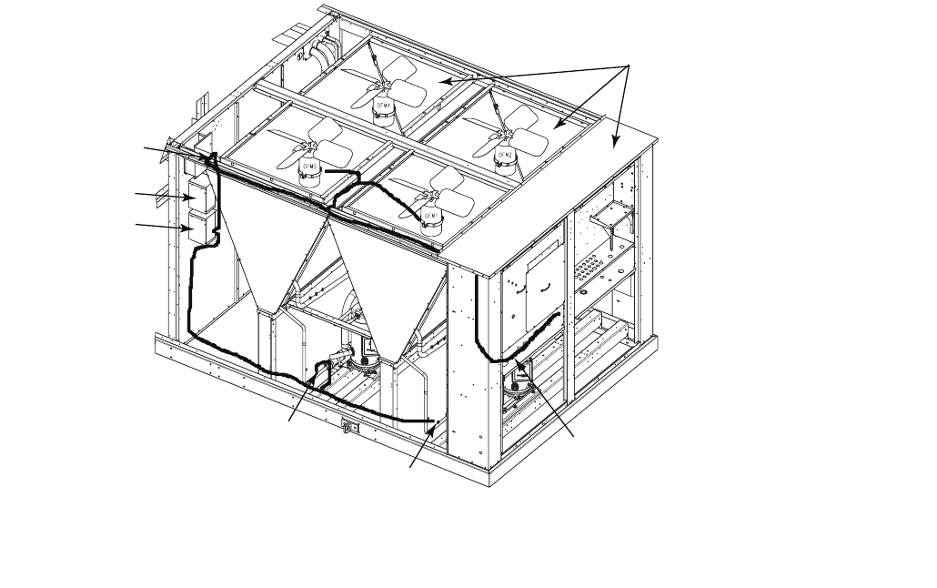
REMOVE PANEL AND
FAN DECKS
MOTORMASTER A
CONTROL
MOTORMASTER B
CONTROL
ROUTE THROUGH
SNAP BUSHING
TRANSDUCER B
TRANSDUCER A
RUN ELECTRICAL HARNESSESUP THE SIDE OF THE UNIT IN THE
SPACE BETWEEN THE CORNER POST AND THE CONTROL BOX.
ROUTE WIRESINTO WIRE TRAY AND RUN TO MMV A/B AND
OFM 3/1
Fig. 9 — MMV Control Mounting — 48/50P070,075 Units
a48-8567