


15
EPM Chip — The drive uses a electronic programming
module (EPM) chip to store the program parameters. This is an
EEPROM memory chip and is accessible from the front of the
VFD. It should not be removed with power applied to the
VFD.
Loss of CCN Communications — Carrier Comfort
Network
®
(CCN) communications with external control
systems can be affected by high frequency electrical noise
generated by the Motormaster
®
V control. Ensure unit is well
grounded to eliminate ground currents along communication
lines.
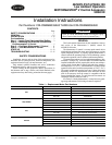
If communications are lost only while Motormaster V con-
trol is in operation, order a signal isolator (CEAS420876-2)
and power supplies (CEAS221045-01, 2 required) for the CCN
communication line.
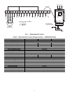
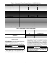
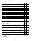
Table 6 — Fault Codes
The drive is programmed to automatically restart after a fault and will attempt to restart three times
after a fault (the drive will not restart after CF, cF, GF, F1, F2-F9, or Fo faults). If all three restart attempts
are unsuccessful, the drive will trip into FAULT LOCKOUT (LC), which requires a manual reset.
LEGEND
CODE DESCRIPTION
RESET
METHOD
PROBABLE CAUSE CORRECTIVE ACTION
AF High Temperature Fault Automatic Ambient temperature is too high;
Cooling fan has failed (if equipped).
Check cooling fan operation.
CF Control Fault Manual A blank EPM, or an EPM with cor-
rupted data has been installed.
Perform a factory reset using Parameter
48 – PROGRAM SELECTION. See Drive
Programming section.
cF Incompatibility Fault Manual An EPM with an incompatible param-
eter version has been installed.
Either remove the EPM or perform a fac-
tory reset (Parameter 48) to change the
parameter version of the EPM to match
the parameter version of the drive.
F1 EPM Fault Manual The EPM is missing or damaged. Install EPM or replace with new EPM.
F2—F9
Fo
Internal Faults Manual The control board has sensed a
problem
Consult factory.
GF Data Fault Manual User data and Carrier defaults in the
EPM are corrupted.
Restore factory defaults by toggling P48 to
another mode. Then set P48 to desired
mode to restore all defaults for that mode.
See Drive Programming section. If that
does not work, replace EPM.
HF High DC Bus Voltage Fault Automatic Line voltage is too high; Deceleration
rate is too fast; Overhauling load.
Check line voltage — set P01
appropriately.
JF Serial Fault Automatic The watchdog timer has timed out,
indicating that the serial link has been
lost.
Check serial connection (computer).
Check settings for P15.
Check settings in communication software
to match P15.
LF Low DC Bus Voltage Fault Automatic Line voltage is too low. Check line voltage — set P01
appropriately.
OF Output Transistor Fault Automatic Phase to phase or phase to ground
short circuit on the output; Failed out-
put transistor; Boost settings are too
high; Acceleration rate is too fast.
Reduce boost or increase acceleration
values. If unsuccessful, replace drive.
PF Current Overload Fault Automatic VFD is undersized for the application;
Mechanical problem with the driven
equipment.
Check line voltage – set P01 appropri-
ately.
Check for dirty coils.
Check for motor bearing failure.
SF Single-phase Fault Automatic Single-phase input power has been
applied to a three-phase drive.
Check input power phasing.
Drive displays
‘---’ even
though drive
should be
running
Start Contact is Not Closed Automatic Start contact is missing or not
functioning.
Check fan relay.
VFD flashes
“---”
and LCS
Start Contact is Not Closed Automatic Start contact not closed. Check FR for closed contact.
VFD flashes
57 (or 47)
and LCS
Speed Signal Lost Automatic Speed signal lost. Drive will operate
at 57 (or 47) Hz until reset or loss of
start command. Resetting requires
cycling start command (or power).
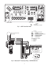
Transducer signal lost. Check VDC signal
between TB5 and TB2. Should be in range
of 0.5V to 4.5V. 5VDC output should be
present between TB6 and TB2.
EPM — Electronic Programming Module
FR — Fan Relay
LCS — Loss of Control Signal
TB — Terminal Block
VFD — Variable Frequency Drive