


11
Step 3 — Configure Motormaster
®
V Con-
trol — The Motormaster V control is configured for propor-
tional integral (PI) control mode. The Motormaster V varies
the condenser fan motor speedto maintain a set point of
320 psig liquid line pressure in response to a 0 to 5 vdc feed-
back signal from the liquid line pressure transducer. No addi-
tional programming is required. See Table 4. Note that the
pressure transducer must be attached for proper configuration.
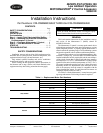
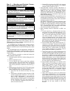
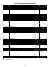
Table 4 — Configuration Table
The following ComfortLink control configurations must be
set when using a Motormaster V device:
• Configuration
COOL
M.M. = YES
• Configuration
COOL
LLAG = CIRCUIT A (size
030-060 units only)
Step 4 — Test Motormaster V Control — To test the
control and motor in the test mode, run compressor no. 1. The
Motormaster V electronic control adjusts the fan speed based
on the liquid line pressure input. Ensure that fans are rotating
clockwise (as viewed from above). If rotation is backward,
lock out all power then swap 2 leads AFTER the Motormaster
V control.
START-UP
The Motormaster V electronic control will be powered up
as long as unit voltage is present. When the system calls for
cooling, the fan relay will be energized to initiate the start-up
sequence for the Motormaster V electronic control. The LED
(light-emitting diode) will display the speed of the motor. The
display range will be 8 to 60 Hz. The Motormaster V electronic
control will start the condenser fan when the compressor en-
gages. The control will adjust the fan speed to maintain ap-
proximately 320 psig. Above that pressure, the fan should op-
erate at full speed.
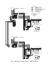
For size 030-060 units, the Motormaster V control uses a 0
to 5 vdc signal input from a pressure transducer attached to the
liquid line service valve gage port on circuit A.
For size 070-100 units, two Motormaster V devices are
used, one for each circuit. The circuit A Motormaster V control
uses a 0 to 5 vdc signal input from a pressure transducer at-
tached to the liquid line service valve gage port on circuit A.
The circuit B Motormaster V control uses a 0 to 5 vdc signal
input from a pressure transducer attached to the liquid line ser-
vice valve gage port on circuit B.
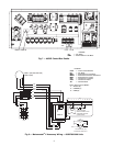
The pressure transducer(s) are connected to terminals 2, 5
and 6 on the controller. The controller is configured by jumper
wires and sensor input types. No field programming is re-
quired. If controller does not function properly, the information
provided below can be used to program and troubleshoot the
drive.
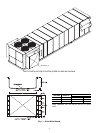
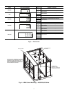
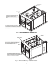
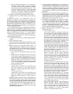
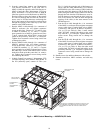
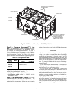
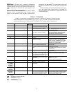
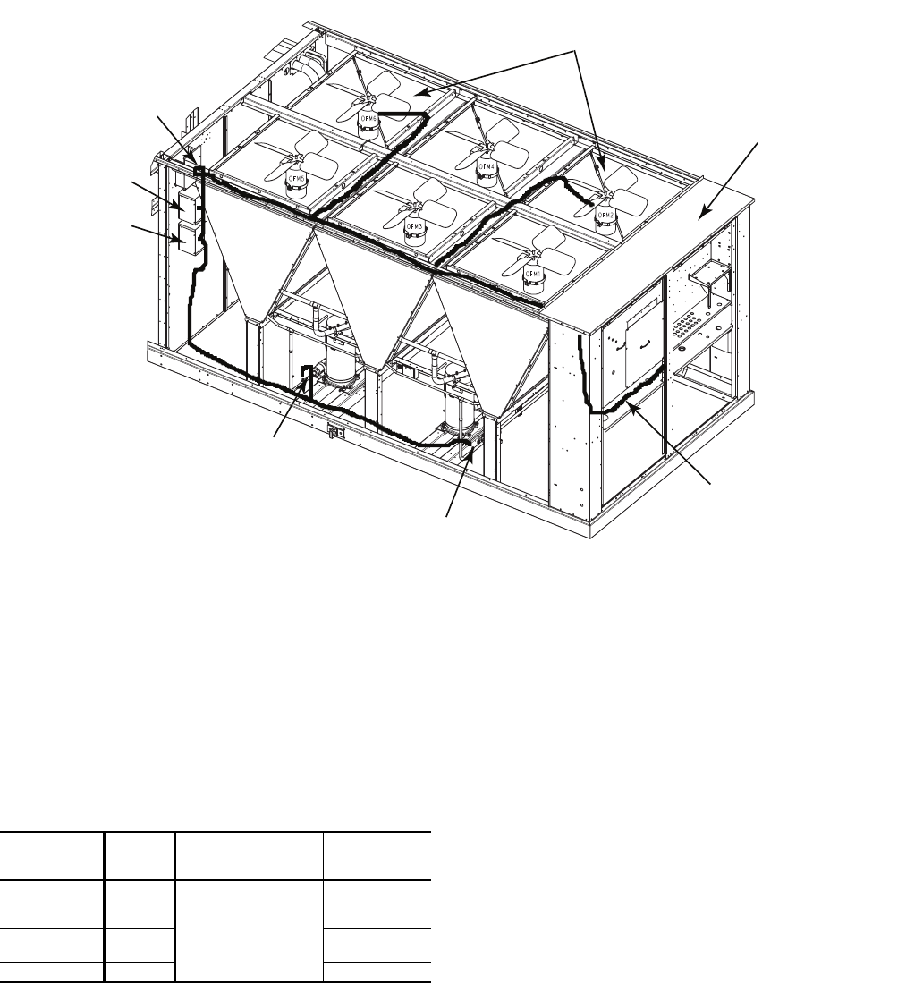
REMOVE TWO FAN DECKS TO
GAIN ACCESS TOROUTE WIRING TO
OFM 2 AND OFM 6
ROUTE THROUGH
SNAP BUSHING
MOTORMASTER A
CONTROL
MOTORMASTER B
CONTROL
TRANSDUCER A
TRANSDUCER B
RUN ELECTRICAL HARNESSES
UP THE SIDE OF THE UNIT
IN THE SPACE BETWEEN THE
CORNER POST AND THE
CONTROL BOX. ROUTE WIRES
INTO WIRE TRAY AND RUN
TO MMV A/B AND OFM 6/2
REMOVE PANEL
Fig. 10 — MMV Control Mounting — 48/50P090,100 Units
a48-8568
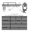
NOMINAL
VOLTAGE
(V-Ph-Hz)
MODE
CONTROL INPUT
(Pin 5)
START
CONTACTS
230-3-60
460-3-60
575-3-60
1
Internal PI control,
0-5V feedback
TB 1,2
208-3-60
380-3-60
2 TB 13A,2
400-3-50 4 TB 13C,2