


5
Step 2 — Mounting and Electrical Connec-
tions for Motormaster® V Control
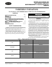
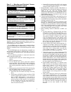
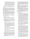
48/50P030-060 UNITS — For 48/50P030-035 units, the Mo-
tormaster controlled outdoor-fan motor (OFM) is the no. 1
OFM (see Fig. 3). The no. 2 OFM is controlled by the Com-
fortlink head pressure control routine.
For 48/50P040 units, the Motormaster controlled outdoor-
fan motor (OFM) is the no. 3 OFM (see Fig. 3). The no. 1 and 2
OFMs are controlled by the Comfortlink head pressure control
routine.
For 48/50P050-060 units, the Motormaster controlled out-
door-fan motor (OFM) is the no. 1 OFM (see Fig. 3). The no. 2,
3, and 4 OFMs are controlled by the Comfortlink head pressure
control routine.
Use the following procedure to mount and connect the
MMV controllers to these units:
1. Disconnect power to the unit. Lockout and tag power dis-
connect.
2. Remove control box covers.
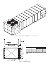
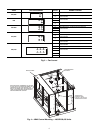
3. For size 030-035 units, remove panel from condenser
section on OFM 1 side of the unit in order to gain access
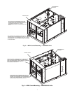
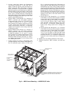
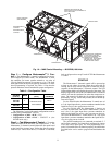
to the outdoor fan section. See Fig. 4. For size 040-060
units, remove panel above control box as shown in Fig. 5
and 6.
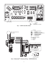
4. Mount accessory fuse block HY11UT035 and fan relay
base HN79KK035 inside control box as shown in Fig. 7.
Secure components with ½-in. sheet metal screws.
a. Insert fuses into fuse blocks and relays into relay
bases.
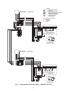
b. Install harness 48EJ402454 from load side of CCB
(control circuit breaker terminals 21, 22, 23) to line
side of MMF (Motormaster V fuse block) as
shown in Fig. 8. Note that it may be easier to pick
up the load side of CCB from the ¼-in. male quick
connect terminals on the line side (terminals 11,
12, 13) of the OFC contactors (see power sche-
matic on control box door).
c. Connect FR (fan relay) coil to OFC1 coil using the
72-in. long 16 gage white and gray wires (stripped
end goes to FR) as shown in Fig. 8.
5. Mount the MMV controller enclosure 30RA500381 on
the bulkhead of the unit inside the outdoor fan section, as
shown in Fig. 4-6, using the mounting brackets
50EJ500656 installed on the enclosure. Remove the en-
closure cover and install the ½-in. HW60EA001 and 1-in.
HW60HH006 connectors in the holes in the lower right
hand side of the enclosure.
6. Connect transducer HK05ZZ001 to the liquid line service
Schrader port of refrigerant Circuit A. Plug transducer ca-
ble 48EJ403240 into transducer. Run cable to the MMV
enclosure, as shown in Fig. 4-6.
Run MMPT (Motormaster V pressure transducer) cable
through ½-in. connector of MMV enclosure (do not tight-
en connector screws at this time). Connect red, green, and
black wires to MMV terminals 6, 5, and 2 as shown in
Fig. 8. Terminate drain wire of transducer cables under
one of the lower MMV mounting screws.
7. Make remaining electrical connections to MMV (see
Fig. 8).
a. In main control box, disconnect black, red, blue,
and green wires from load side (terminals 21, 22,
23) of OFC1 (sizes 030-035, 050-060) contactor or
OFC 3 (size 040) (label cable from OFC1 or OFC3
(size 040) as OFM1 or OFM3 (size 040). Pull
wires out through the hole in the bottom of the
control box and run them up the corner post to the
opening of the cable tray on the side of the control
box, as shown in Fig. 4-6. Run the cable through
the wire tray to the MMV enclosures.
b. Run the OFM1/OFC3 (040) cable through the 1-in.
connector of the MMV enclosure (do not tighten
connector screws at this time). Remove ring termi-
nals from black, red, and blue wires and strip insu-
lation back 3/8-in. Connect black, red, and blue
wires to MMV terminals T1, T2, and T3. Connect
green ground wire to MMV ground screw.
c. In the main control box connect Motormaster VFD
(variable frequency drive) harness 48ZZ401971 to
the load side of the MMF (label the opposite end of
this harness as MMF). Run the harness along the
bottom of the control box and out through the hole
that the OFM harness was in. Pull the harness out
through the hole in the bottom of the control box
and run it through the opening of the cable tray (in
the same manner as the OFM harnesses).
d. Run the MMF cable through 1-in. connector of the
MMV enclosure (do not tighten connector screws
at this time). Connect L1, L2, and L3 wires to
MMV terminals L1, L2, and L3. Connect green
ground wire to MMV ground screw. Place 1 large
varnish cloth 48DA510141 around both cables at
the point they enter the 1-in. connector. Tighten
down connector screws being careful not to dam-
age the cables.
e. In the main control box connect one Motormaster
VFD harness 48ZZ402001 to the NO (normally
open) contact of the FR (see Fig. 8). Run the har-
nesses along the bottom of the control box and out
through the hole that the OFM harness was in. Pull
the harness out through the hole in the bottom of
the control box and run it through the opening of
the cable (in the same manner as the OFM
harness).
WARNING
To avoid possibility of electric shock and personal
injury, open and tag all electrical disconnects before
installing or servicing unit.
WARNING
Hazard of electric shock. Wait three minutes after discon-
necting incoming power before servicing drive. Capacitors
retain charge after power is removed.
CAUTION
To avoid damage to the small terminals on the Motormas-
ter V control, use care when tightening the compression
terminals and use the proper size screwdriver.
CAUTION
DO NOT connect incoming AC power to Motormaster V
output terminals T1, T2, and T3. Severe damage to the con-
trol will result.