


7
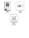
TO INSTALL THERMOSTAT:
If there is at least
3
/
8
in. of space between the back of indoor
unit and wall:
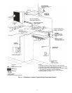
1. Route thermostat wires (field-supplied) through slot in
right side or rear panel of indoor unit (Fig. 3).
2. Route wires over refrigerant and drain piping as shown
in Fig. 12.
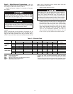
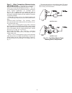
Step 4 — Connect Refrigerant Piping — Fan coil
units may be connected to outdoor units using field-supplied
refrigerant grade piping. Refer to Tables 3A and 3B for the cor-
rect size piping. The length of refrigerant pipe depends on the
unit placement and building structure; run pipes as directly as
possible. For piping requirements over 50 ft of total run, or
more than 25 ft of lift, consult the Residential Long Line Appli-
cation Guide.
To connect piping:
1. Install insulation. It is extremely important that all
refrigerant lines and the metering device be insulated
on heat pumps and multi-splits. On cooling only units,
the liquid line may be left uninsulated. Use any accept-
able heat resistant closed-cell foam insulation (mini-
mum
3
/
8
-in. wall thickness). When insulating piping,
cap ends and slide insulation over the piping. Insula-
tion can also be cut and placed over piping.
2. Run liquid and gas refrigerant piping.
a. Run pipes as directly as possible, and avoid any
unnecessary turns and bends.
b. Suspend refrigerant pipes so that the insulation is
not damaged and vibrations are not transmitted to
the structure.
c. Leave slack in the refrigerant pipe between the
structure and the unit to absorb vibrations.
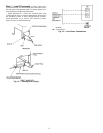
d. A piston is shipped in the factory-installed meter-
ing device body (Fig. 13) with the indoor unit. Use
Tables 4A-4C to verify that you have the required
piston size for the system being installed.
e. For special applications such as long lines or raised
elevations, consult the Residential Long Line
Application Guide for specific system require-
ments. The arrow on the metering device body
must face away from the indoor coil.
IMPORTANT: Do not route wires under the piping, or
wires could impede air filter removal.
DO NOT BURY MORE THAN 36 IN. OF REFRIGER-
ANT PIPE IN THE GROUND. If any section of pipe is
buried, there must be a 6-in. vertical rise to the valve con-
nections on the outdoor unit. If more than the recommended
length is buried, refrigerant may migrate to the cooler, bur-
ied section during extended periods of unit shutdown, caus-
ing refrigerant slugging and possible compressor damage at
start-up.
IMPORTANT: The metering device is factory-
installed and only needs to be replaced for long line
applications or if the system combination requires it.
See Tables 4A-4C. See Fig. 13.
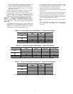
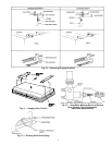
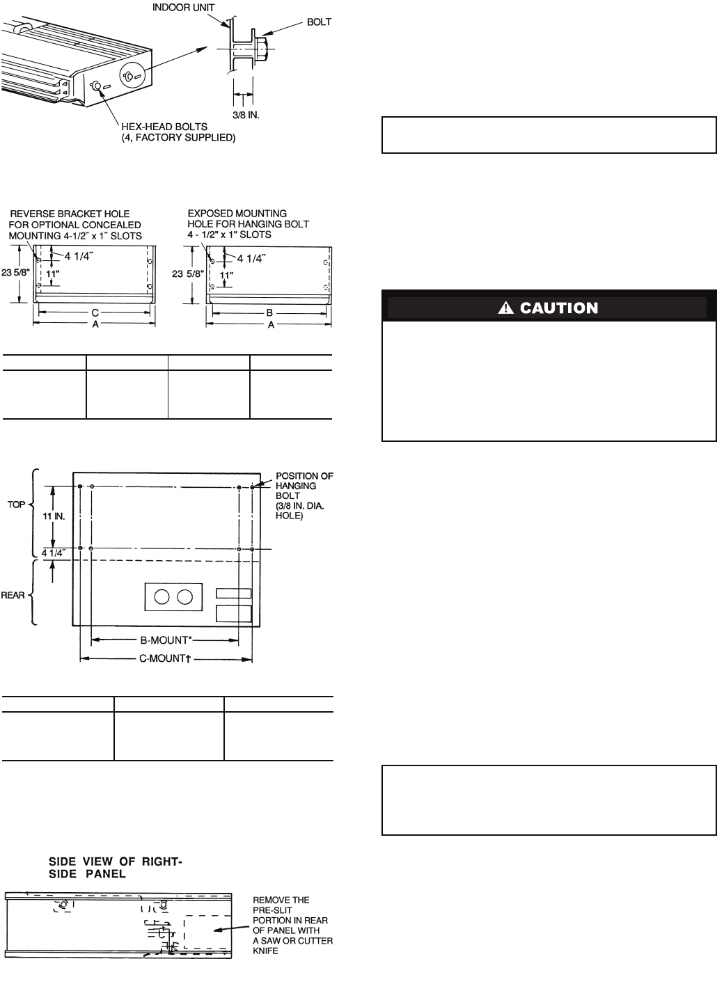
Fig. 6 — Installing Hex-Head Mounting Bolts
in Fan Coil Unit
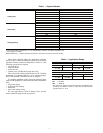
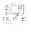
DIMENSIONS (in.)
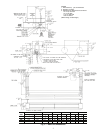
Fig. 7 — Fan Coil Unit Hanging Dimensions
UNIT SIZE A B C
024 50
15
/
16
46 49
5
/
8
036 58
13
/
16
53
7
/
8
57
1
/
2
048 71
9
/
16
66
5
/
8
70
1
/
4
060 92 87 90
5
/
8
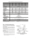
DIMENSIONS (in.)
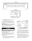
*Exposed mounting holes.
†Reverse bracket holes (concealed mounting).
Fig. 8 — Mounting Included with
Fan Coil Unit
UNIT SIZE B C
024 46 49
5
/
8
036 53
7
/
8
57
1
/
2
048 66
5
/
8
70
1
/
4
060 87 90
5
/
8
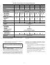
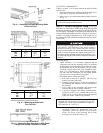
Fig. 9 — Removing Rear Knockout in Side Panel
if Right-Side Piping Connection is Used